Figure 13-5. x62 mode 6 (latch) timing example -52 – Basler Electric BE1-700 User Manual
Page 348
Command
Purpose
S0-62=30s
Sets T1 at 30 seconds.
EXIT;Y
Exit and save settings.
Step 2: Transmit the commands in Table 13-93 to the relay. These commands supply a latch input to
the 62 Timer by changing the 43 Switch state to TRUE. By changing the BLK input (143 Switch)
to TRUE, these commands supply a reset command, also.
Table 13-93. x62 Mode 6 Timer Initiate Commands
Command
Purpose
A=
Gains write access.
CS-43=P
Selects 43 for pulse operation.
CO-43=P
Executes 43 pulse operation.
Execute the following commands in less than 30 seconds.
CS-43=P
Selects 43 for pulse operation.
CO-43=P
Executes 43 pulse operation.
Wait at least 30 seconds (total elapsed time) to initiate the block command.
CS-143=P
Selects 143 for pulse operation.
CO-143=P
Executes 143 pulse operation.
EXIT
Exit the select and operate mode.
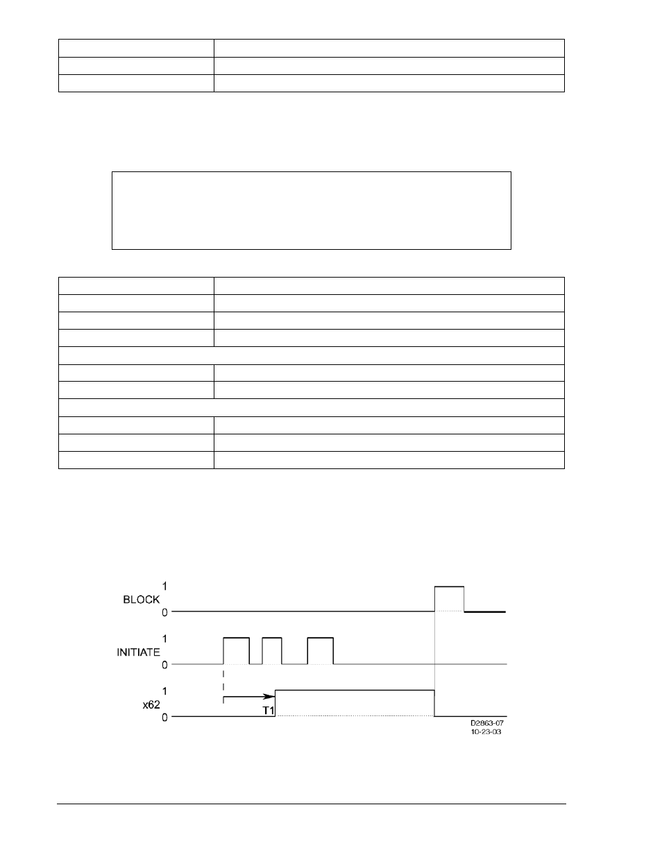
Step 3: Use the RS-LGC command to obtain an SER report and verify that the following actions were
logged. These events are illustrated in the timing diagram of Figure 13-5.
Timer T1 continued to time out after the first 43 Switch action. (TRUE).
Timer T1 timed out and the 62 Timer output went TRUE 30 seconds after 43 Switch action.
(TRUE). Timer output 62 returned to a FALSE state with the 143 Switch action (TRUE).
Figure 13-5. x62 Mode 6 (Latch) Timing Example
Step 4: (Optional.) Repeat the 62 Timer tests for Modes 1, 2, 3, and 5 for Setting Group 1.
NOTE
The CS and CO commands of Table 13-93 are performed twice in this test.
Follow the timing sequence to illustrate time mode action. The time delay settings
may be increased if difficulty is encountered with repeating the 43 and 143
Switch actions.
13-52
BE1-700 Testing and Maintenance
9376700990 Rev M