25vm - voltage monitor, 25vm - voltage monitor -59 – Basler Electric BE1-700 User Manual
Page 115
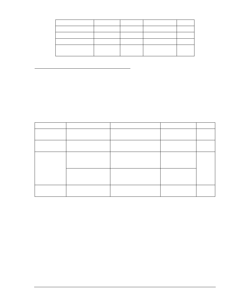
Table 4-33. Operating Settings for Sync-Check Protection
Setting
Range
Increment
Unit of Measure
Default
Delta Voltage
1 to 20
0.1
Secondary volts
1
Delta Angle
1 to 99
0.1
Degrees
10
Slip Frequency
0.01 to 0.5
0.01
Hertz
0.01
Phase Frequency >
Aux Frequency
0 = Disabled
1 = Enabled
N/A
N/A
0
Retrieving Sync-Check Protection Status from the Relay
The status of each logic variable can be determined through the ASCII command interface using the RG-
STAT (report general-status) command. See Section 6, Reporting and Alarm Functions, General Status
Reporting, for more information. The status can also be determined using BESTCOMS Metering screen.
25VM - Voltage Monitor
Operating settings for the 25VM are made on the Voltage Protection screen at the 25 tab. Refer to Figure
4-57. Settings can also be made with the S0-25VM ASCII command or on HMI Screens 5.x.2.2 – 5.x.2.4.
Table 4-34 summarizes the operating settings for Voltage Monitor.
Table 4-34. Operating Settings for Voltage Monitor
Setting
Range
Increment
Unit of Measure
Default
Live
10 to 150
0.1 for 10 to 100
1 for 100 to 150
Volts
60
Dead
10 to 150
0.1 for 10 to 100
1 for 100 to 150
Volts
20
Dropout Delay
50 to 60000
1 for 50 to 999
100 for 1000 to 9900
1000 for 10000 to 60000
Milliseconds
50 ms
0.050 to 60
0.001 for 0.050 to 0.999
0.1 for 1.0 to 9.9
1 for 10 to 60
Seconds
25VM1
0 = Disabled
1 – 3, 12, 13, 23, 123
N/A
N/A
0
The sync-check output, 25, only provides closing supervision for the live line/live bus condition. The
voltage monitor function 25VM is provided for conditions where the bus and/or the line are dead. A live
condition for either the VP or the VX is determined when the measured voltage on the respective input is
above the measured voltage and below the DV threshold.
For the phase voltage input, if the connection is three phase, 3W, or 4W, all three phases are tested and
must be above the LV threshold for a live condition to be TRUE. Similarly, all three phases must be below
the DV threshold for a dead condition to be TRUE.
The function includes one independent output, 25VM1 as illustrated in Figure 4-58. The logic conditions
are summarized in Table 4-35. Any combination of logic settings can be selected as shown in Table 4-34.
When a logic condition is selected, it closes the respective switch in Figure 4-58 associated with each of
the outputs. The two independent logic outputs might be used to set up different closing supervision
criteria for automatic reclose versus manual close.
9376700990 Rev M
BE1-700 Protection and Control
4-59