Negative-sequence voltage (47) (be1-700v), Negative-sequence voltage (47) (be1-700v) -35, Table 13-56. 47 pickup test commands -35 – Basler Electric BE1-700 User Manual
Page 331: Table 13-55
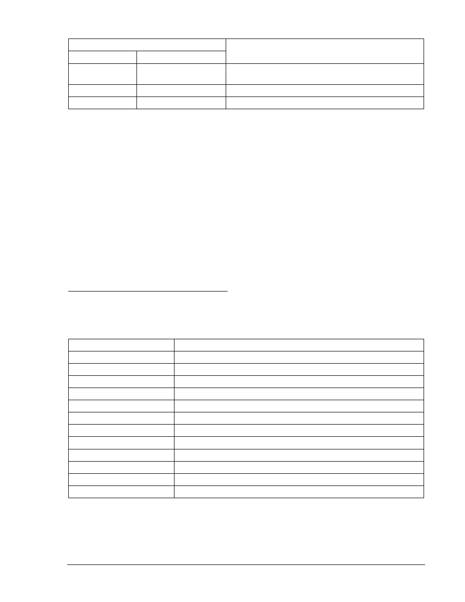
Table 13-55. 27X and 59X/159X Pickup and Time Delay Settings
Pickup and Time Delay Settings
Purpose
Undervoltage
Overvoltage
S0-27X=50,2S,0
S0-59X/159X=110,2S
Sets 27X PU at 50 V, 59X/159X at 110 V, TD at 2 sec,
UV Inhibit disabled.
S0-27X=,5S
S0-59X/159X=,5S
Sets 27X PU at 50 V, 59X/159X at 110 V, TD at 5 sec.
S0-27X=,10S
S0-59X159X=,10S
Sets 27X PU at 50 V, 59X/159X at 110 V, TD at 10 sec.
Step 2: Prepare to monitor the 27X and 59X/159X timings. Timing accuracy is verified by measuring the
elapsed time between a sensing voltage change and OUT1 closing.
Step 3: Connect and apply a single-phase, 80 Vac, 3
rd
harmonic voltage source to Terminals C17
(polarity) and C18 (non-polarity). Refer to Figure 12-4 for terminal locations.
Step 4: Step the voltage down to 45 volts. Measure the time delay and verify the accuracy of the 27X
time delay setting. Timing accuracy is
±5% or ±3 cycles of the time delay setting.
Step 5: Step the voltage up to 115 volts. Measure the time delay and verify the accuracy of the
59X/159X time delay setting. Timing accuracy is
±5 percent or ±3 cycles of the time delay
setting.
Step 6: Repeat Steps 5 and 6 for the middle and upper time delay settings of Table 13-55.
Step 7: (Optional.) Repeat Steps 2 through 6 for Setting Group 1.
Negative-Sequence Voltage (47) (BE1-700V)
Purpose: To verify the operating accuracy of the 47 protection element.
Reference Commands: SL-47, SL-VO, SL-GROUP, RG-STAT
Negative-Sequence Voltage Pickup Verification
Step 1: Prepare the 47 pickup function for testing by transmitting the commands in Table 13-56 to the
relay. Reset targets.
Table 13-56. 47 Pickup Test Commands
Command
Purpose
A=
Gains write access.
SL-N=NONE
Zero out custom logic settings. Overwrite with LOGIC=NONE settings.
Y
Confirm overwrite.
SL-N=47
Sets 47 as custom logic name.
SL-27P=0
Disables 27P.
SL-59P=0
Disables 59P.
SL-47=1,0
Enables 47, disables blocking.
SP-60FL=ENA,PN
Removes 60FL block from 47 element.
SL-VO1=47T
Enables OUT1 to close for 47 trip.
SG-TRIG=47T,47PU,0
Enables 47 to log and trigger fault recording.
SG-TARG=47
Enables 47 target.
EXIT;Y
Exit and save settings.
Step 2: Using Table 13-57 as a guide, transmit the first row of setting commands to the relay.
9376700990 Rev M
BE1-700 Testing and Maintenance
13-35