Basler Electric BE1-700 User Manual
Page 66
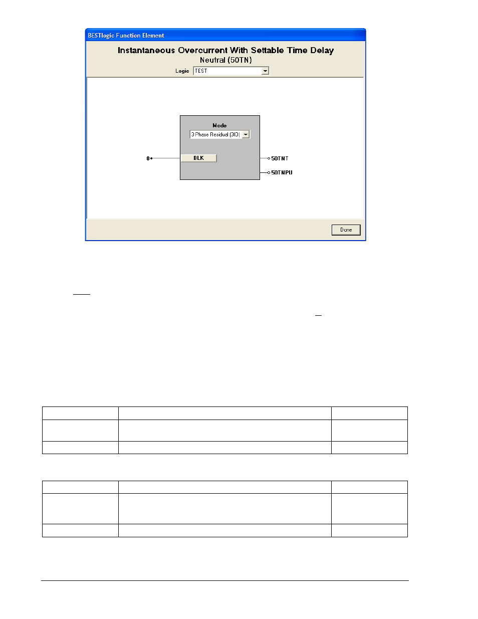
Figure 4-7. BESTlogic Function Element Screen, Neutral (50TN)
At the top center of the BESTlogic Function Element screen is a pull-down menu labeled Logic. This
menu allows viewing of the BESTlogic settings for each preprogrammed logic scheme. A custom logic
scheme must be created and selected in the Logic pull-down menu at the top of the screen before
BESTlogic settings can be changed. See Section 7, BESTlogic Programmable Logic.
Enable the 50T or 150T function by selecting its mode of operation from the Mode pull-down menu. To
connect the element's inputs, select the button for the corresponding input in the BESTlogic Function
Element screen. The BESTlogic Expression Builder screen will open. Select the expression type to be
used. Then, select the BESTlogic variable, or series of variables to be connected to the input. Select
Save when finished to return to the BESTlogic Function Element screen. For more details on the
BESTlogic Expression Builder, See Section 7, BESTlogic Programmable Logic. Select Done when the
settings have been completely edited. Tables 4-4, 4-5, and 4-6 summarize the BESTlogic Settings for the
Phase, Neutral, and Negative-Sequence elements.
Table 4-4. BESTlogic Settings for 50TP/150TP Instantaneous Overcurrent Protection
Function
Range/Purpose
Default
Mode
0 = Disabled
1 = Enabled
1
BLK
Logic expression that disables function when TRUE.
0
Table 4-5. BESTlogic Settings for 50TN/150TN Instantaneous Overcurrent Protection
Function
Range/Purpose
Default
Mode
0 = Disabled
1 = 3-phase residual (3IO)
G = Ground input
1
BLK
Logic expression that disables function when TRUE.
0
4-10
BE1-700 Protection and Control
9376700990 Rev M