Basler Electric BE1-700 User Manual
Page 122
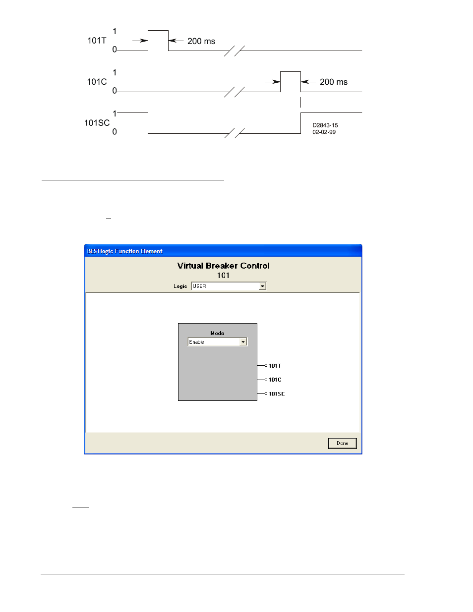
Figure 4-65. Virtual Breaker Control Switch State Diagram
BESTlogic Settings for Virtual Breaker Control Switch
BESTlogic settings are made from the BESTlogic Function Element screen in BESTCOMS. Figure 4-66
illustrates the BESTCOMS screen used to select BESTlogic settings for the Breaker Control Switch
element. To open the BESTlogic Function Element screen for the Virtual Switch element, select Virtual
Switches from the Screens pull-down menu. Then select the BESTlogic button for the virtual switch to be
edited. Alternately, settings may be made using the SL-101 ASCII command.
Figure 4-66. BESTlogic Function Element Screen, 101
At the top center of the BESTlogic Function Element screen is a pull-down menu labeled Logic. This
menu allows viewing of the BESTlogic settings for each preprogrammed logic scheme. A custom logic
scheme must be created and selected in the Logic pull-down menu at the top of the screen before
BESTlogic settings can be changed. See Section 7, BESTlogic Programmable Logic.
Enable the Virtual Breaker Control function by selecting its mode of operation from the Mode pull-down
menu. Select Done when the settings have been completely edited.
Table 4-39 summarizes the BESTlogic settings for Virtual Breaker Control Switch.
4-66
BE1-700 Protection and Control
9376700990 Rev M