Figure 4-9. time overcurrent logic blocks -13 – Basler Electric BE1-700 User Manual
Page 69
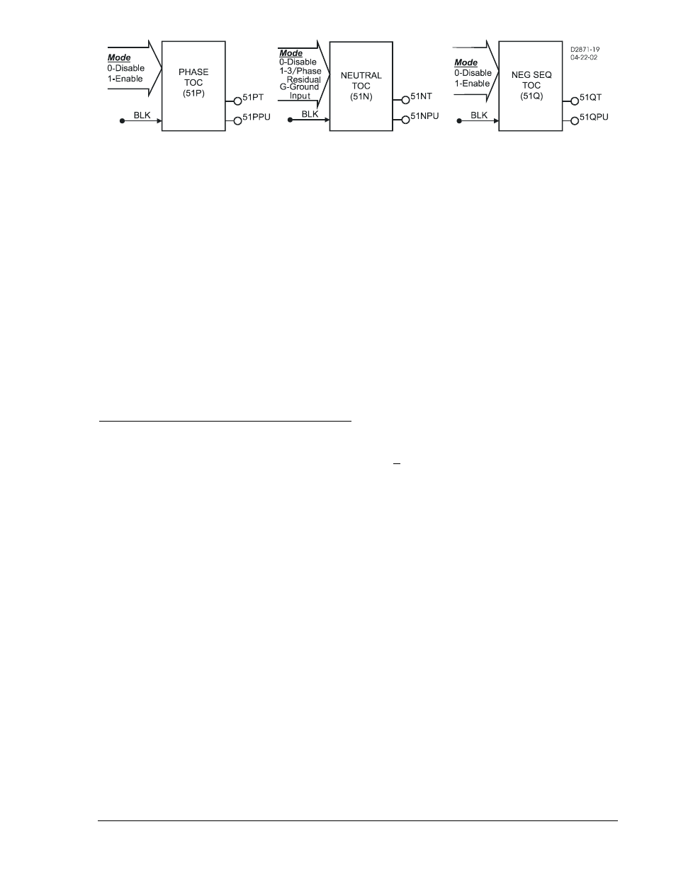
Figure 4-9. Time Overcurrent Logic Blocks
Each inverse time overcurrent function has a Mode, Pickup, Time Dial and Curve setting. See Appendix
A, Time Overcurrent Characteristic Curves, for details on each of the curves available. To make the
protective element use integrated reset and emulate an electromechanical induction disk reset
characteristic, the user can append an R to the selected time current characteristic curve designation. An
available programmable curve can be used to create a custom curve by selecting coefficients in the
inverse time characteristic equation.
When the measured current is above the pickup threshold, the pickup logic output is TRUE and inverse
timing is started according to the selected characteristic. If the current stays above pickup until the
element times out, the trip logic output becomes TRUE. If the current falls below the dropout ratio, which
is 95 percent, the function will either reset instantaneously or begin timing to reset depending on the
user's setting.
The phase overcurrent protective functions use the highest of the three measured phase currents. If the
current is above the pickup setting for any one phase, the pickup logic output is asserted. If the trip
condition is TRUE, the trip logic output is asserted.
If the target is enabled for an element, the target reporting function will record a target for all phases that
are above pickup when the protective function trip output is TRUE and the fault recording function trip
logic expression is TRUE. See Section 6, Reporting and Alarm Functions, Fault Reporting, for more
details on the target reporting function.
BESTlogic Settings for Time Overcurrent Protection
BESTlogic settings are made from the BESTlogic Function Element screen in BESTCOMS. Figure 4-10
illustrates the BESTCOMS screen used to select BESTlogic settings for the Time Overcurrent function.
To open the screen, select Overcurrent Protection from the Screens pull-down menu and select either 51
or 151 tab. Then select the BESTlogic button at the bottom of the screen that corresponds with the
element to be modified. Alternately, settings may be made using the SL-51 and SL-151 ASCII commands.
9376700990 Rev M
BE1-700 Protection and Control
4-13