Digital input conditioning function, Digital input conditioning function -5, Table 3-2. contact-sensing turn-on voltages -5 – Basler Electric BE1-700 User Manual
Page 45
Energizing levels for the contact-sensing inputs operate at a minimum of approximately 5 Vdc for 24 Vdc
nominal sensing voltages, 26 Vdc for 48 Vdc nominal sensing voltages, 69 Vdc for 125 Vdc nominal
sensing voltages, or 138 Vdc for 250 Vdc nominal sensing voltages. See Table 3-2 for the contact-
sensing turn-on voltages.
Table 3-2. Contact-Sensing Turn-On Voltages
Style Option
Nominal Input Voltage
Contact-Sensing Turn-On Voltage †
xxx1xxx
48 Vdc
26 to 38 Vdc
xxx2xxx
125 Vac/dc
69 to 100 Vdc
56 to 97 Vac
xxx3xxx
24 Vdc
Approx. 5 Vdc
xxx4xxx
250 Vac/dc
138 to 200 Vdc
112 to 194 Vac
xxx5xxx
125 Vac/dc
*
69 to 100 Vdc
56 to 97 Vac
* Extended holdup option. See Style Chart in Figure 1-1.
† AC voltage ranges are calculated using the default recognition time (4 ms) and debounce time (16 ms).
Digital Input Conditioning Function
Status of the contact sensing inputs is checked 12 times per cycle. (See Figure 3-3.) When operating on a
60 hertz power system, the result is the input status being sampled every 1.4 milliseconds (1.6
milliseconds on 50 hertz systems). User-settable digital contact recognition and debounce timers
condition the signals applied to the inputs. These parameters can be adjusted to obtain the optimum
compromise between speed and security for a specific application. Digital input conditioning is evaluated
every quarter cycle.
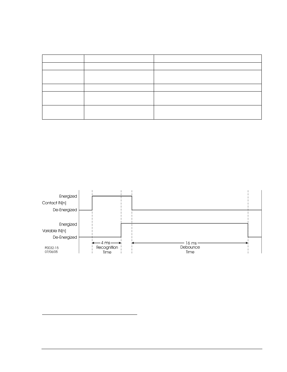
Figure 3-3. Digital Input Conditioning Timing Diagram
If the sampled status of a monitored contact is detected as energized for the recognition time, the logic
variable changes from a de-energized (logic 0 or FALSE) state to an energized (logic 1 or TRUE) state.
Once contact closure is recognized, the logic variable remains in the energized state until the sampled
status of the monitored contact is detected to be de-energized for a period that is longer than the
debounce time. At this point, the logic variable will change from an energized (logic 1 or TRUE) state to a
de-energized (logic 0 or FALSE) state.
Setting the Digital Input Conditioning Function
Settings and labels for the digital input conditioning function are set using BESTCOMS. Alternately,
settings may be made using the SG-IN ASCII Command.
Each of the four inputs has two settings and three labels. The settings are Recognition Time and
Debounce Time. The labels include a label to describe the input, a label to describe the Energized State,
and a label to describe the De-Energized State. Labels are used by the BE1-700's reporting functions.
9376700990 Rev M
BE1-700 Input and Output Functions
3-5