Basler Electric BE1-700 User Manual
Page 83
If the 60FL element trip logic is TRUE, and V block is enabled for phase blocking (P), all functions that
use the phase voltage are blocked. For more information on the 60FL function, see the paragraphs later
in this section.
If the target is enabled for the element, the target reporting function will record a target for all phases that
are picked up when the protective function trip output is TRUE and the fault recording function trip logic
expression is TRUE. See Section 6, Reporting and Alarm Functions, Fault Reporting, for more
information about target reporting.
When undervoltage inhibit is selected, undervoltage sensing is disabled for any phase that falls below the
inhibit threshold. Undervoltage inhibiting is disabled when the threshold is set to zero. Undervoltage inhibit
is used to prevent undesired undervoltage tripping, such as when a loss of supply occurs.
BESTlogic Settings for Phase Undervoltage/Overvoltage Protection
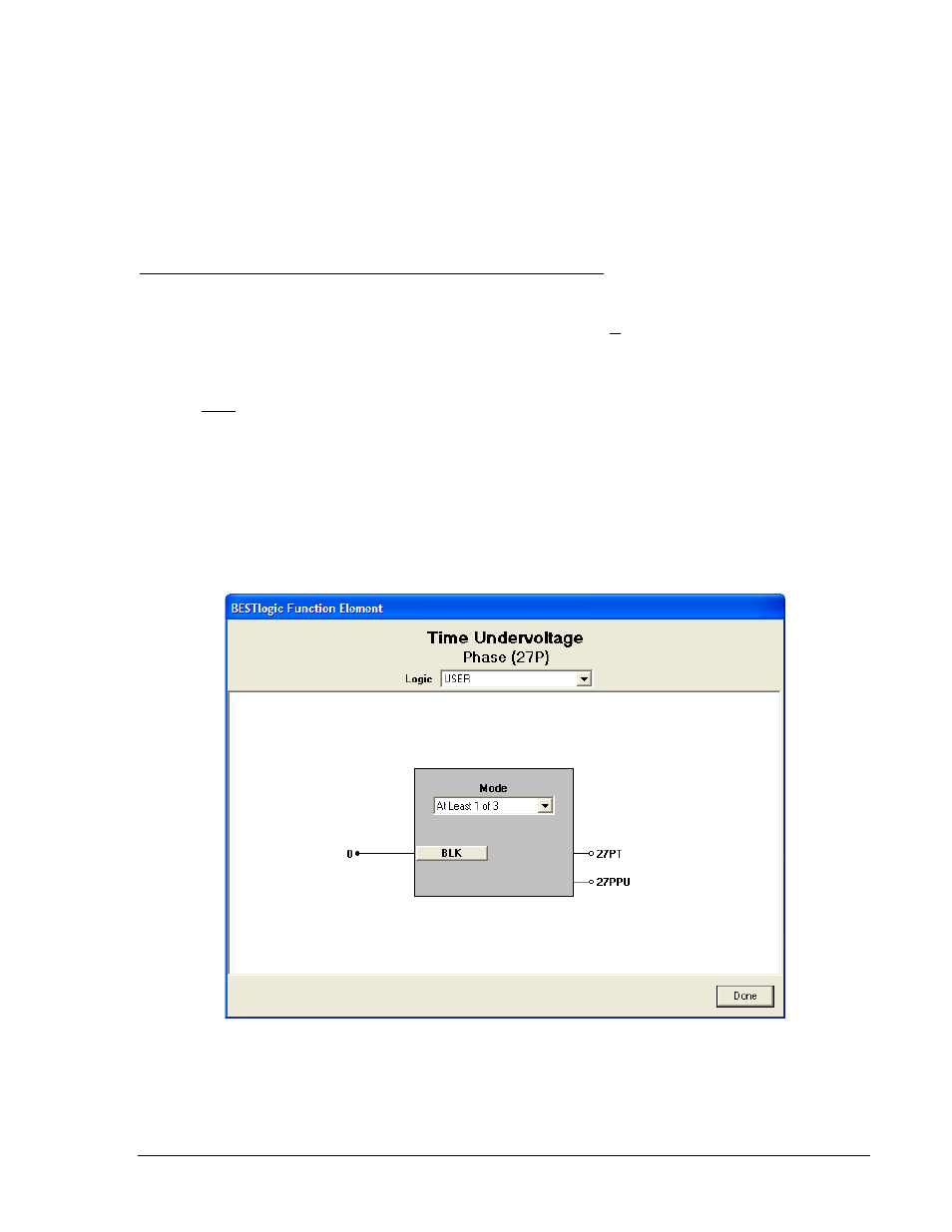
BESTlogic settings are made from the BESTlogic Function Element screen in BESTCOMS. Figure 4-23
illustrates the BESTCOMS screen used to select BESTlogic settings for the Under and Overvoltage
elements. To open the screen, select Voltage Protection from the Screens pull-down menu, and select
the 27P/127P tab. Alternately, settings may be made using the SL-27P and SL-59P ASCII commands.
At the top center of the BESTlogic Function Element screen is a pull-down menu labeled Logic. This
menu allows viewing of the BESTlogic settings for each preprogrammed logic scheme. A custom logic
scheme must be created and selected in the Logic pull-down menu at the top of the screen before
BESTlogic settings can be changed. See Section 7, BESTlogic Programmable Logic.
Enable the element by selecting its mode of operation from the Mode pull-down menu. To connect the
elements inputs, select the button for the corresponding input in the BESTlogic Function Element screen.
The BESTlogic Expression Builder screen will open. Select the expression type to be used. Then, select
the BESTlogic variable, or series of variables to be connected to the input. Select Save when finished to
return to the BESTlogic Function Element screen. For more details on the BESTlogic Expression Builder,
see Section 7, BESTlogic Programmable Logic. Select Done when the settings have been completely
edited.
Figure 4-23. BESTlogic Function Element Screen, Phase (27P)
Table 4-16 summarizes the BESTlogic settings for Phase Undervoltage/Overvoltage Protection.
9376700990 Rev M
BE1-700 Protection and Control
4-27