Basler Electric BE1-700 User Manual
Page 102
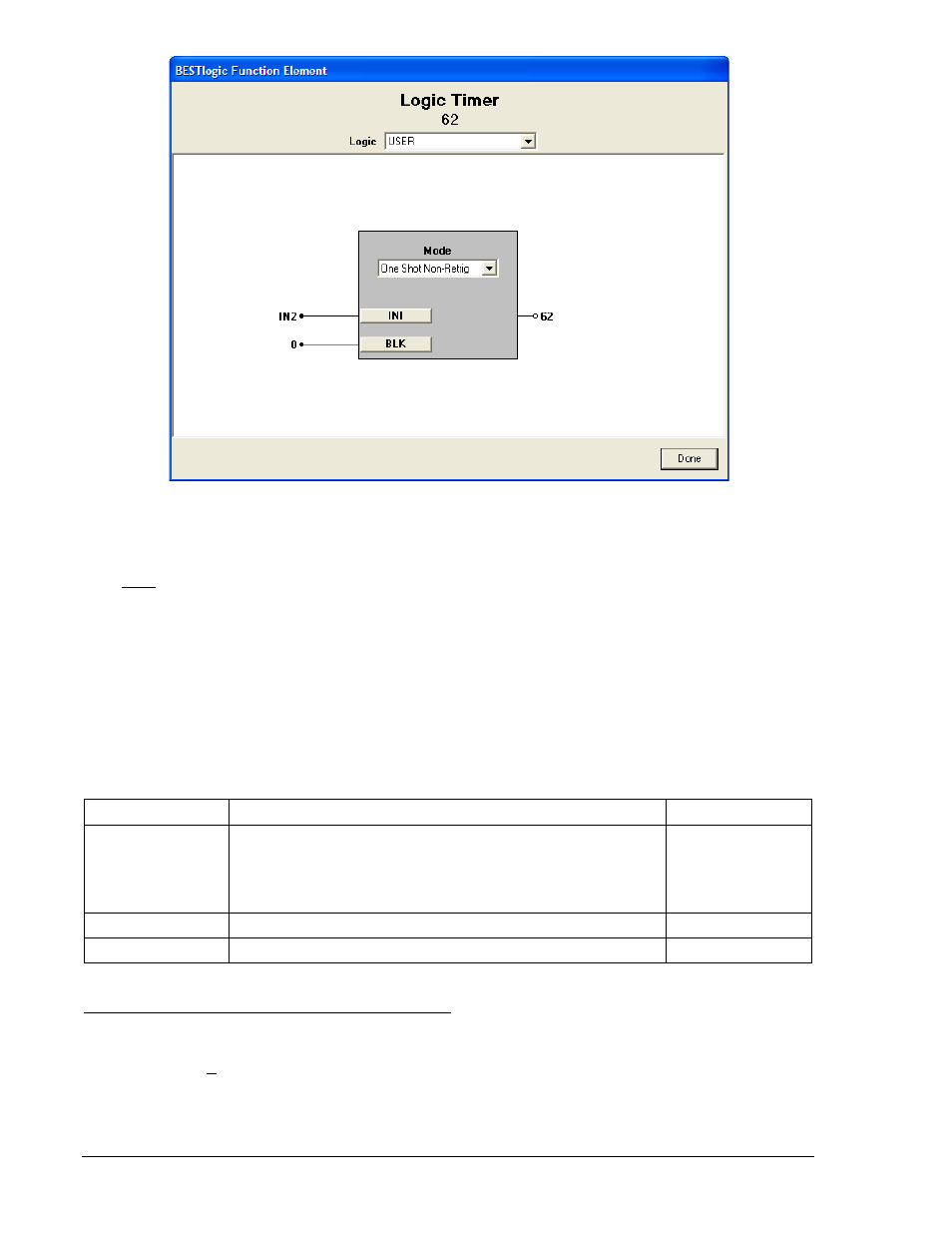
Figure 4-44. BESTlogic Function Element Screen, 62
At the top center of the BESTlogic Function Element screen is a pull-down menu labeled Logic. This
menu allows viewing of the BESTlogic settings for each preprogrammed logic scheme. User or custom
logic must be selected on this menu in order to allow changes to the mode and inputs of the element.
Enable the Logic Timer function by selecting its mode of operation from the Mode pull-down menu.
To connect the element's inputs, select the button for the corresponding input in the BESTlogic Function
Element screen. The BESTlogic Expression Builder screen will open. Select the expression type to be
used. Then, select the BESTlogic variable, or series of variables to be connected to the input. Select
Save when finished to return to the BESTlogic Function Element screen. For more details on the
BESTlogic Expression Builder, see Section 7, BESTlogic Programmable Logic. Select Done when the
settings have been completely edited.
Table 4-27 below summarizes the BESTlogic settings for General Purpose Logic Timers.
Table 4-27. BESTlogic Settings for General Purpose Logic Timers
Function
Range/Purpose
Default
Logic Mode
0 = Disabled
1 = PU/DO
2 = One Shot Non-Retrig
3 = One Shot Retrig
4 = Oscillator
5 = Integrating
6 = Latch
0
INITIATE
Logic expression that initiates timing sequence.
0
BLOCK
Logic expression that disables function when TRUE.
0
Operating Settings for General Purpose Logic Timers
Operating settings are made using BESTCOMS. Figure 4-45 illustrates the BESTCOMS screen used to
select operational settings for the Logic Timers element. To open the Logic Timers screen, select Logic
Timers from the Screens pull-down menu. Alternately, settings may be made using the S<g>-62/162
ASCII command or through the HMI interface using Screens 5.1.9.1 and 5.1.9.2.
4-46
BE1-700 Protection and Control
9376700990 Rev M