Bestlogic settings for setting group control, Bestlogic settings for setting group control -2, Figure 4-1. setting group control logic block -2 – Basler Electric BE1-700 User Manual
Page 58
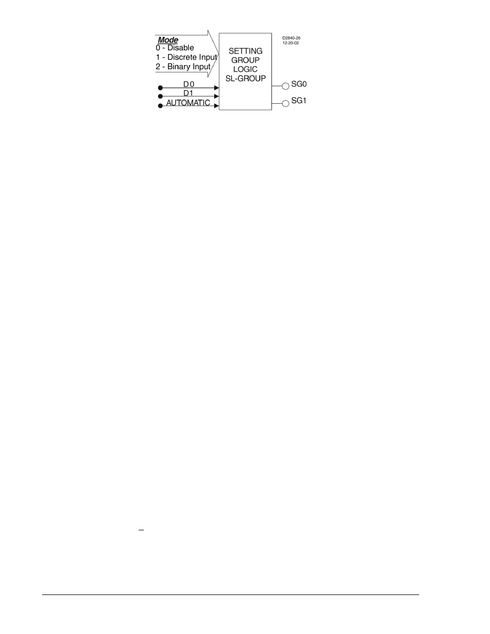
Figure 4-1. Setting Group Control Logic Block
The group of settings that is active at any point in time is controlled by the setting group control logic. This
function logic allows for manual (logic) control. The function monitors logic inputs, D0 and D1 and
changes the active setting group according to the status of these inputs. These inputs can be connected
to logic expressions such as contact sensing inputs.
The function logic has two logic variable outputs, SG0 and SG1. The appropriate variable is asserted
when each setting group is active. These logic variables can be used in programmable logic to modify the
logic based upon which setting group is active. For example, it may be desirable for the 51P element to
trip the low-side breaker through OUT2 under normal conditions but to trip the 86T lockout relay through
OUT1 when in Setting Group 1. To accomplish this, the logic for OUT1 would include the term 51PTSG1
so that 51PT actuates only when SG1 is active.
The setting group control function logic also has an alarm output variable SGC (Setting Group Changed).
This output is asserted whenever the BE1-700 switches from one setting group to another. The SGC
alarm bit is asserted for the SGCON time setting. This output can be used in the programmable alarms
function if it is desired to monitor when the BE1-700 changes to a new setting group. See Section 6,
Reporting and Alarm Functions, Alarms Function, for more information on using alarm outputs.
The SGCON time setting also serves to provide anti-pump protection to prevent excessive changing
between groups. Once a change in active group has been made, another change cannot take place for
two times the SGCON setting.
The SGC ACTIVE alarm output is typically used to provide an external acknowledgment that a setting
group change occurred. If SCADA (Supervisory Control and Data Acquisition) is used to change the
active group, then this signal could be monitored to verify that the operation occurred. The SGC ACTIVE
alarm output ON time is user programmable and should be set greater than the SCADA scan rate. This
can be set through the BESTCOMS graphical user interface (GUI). Alternately, it can be set using the
SG-SGCON (settings general–SGC Alarm on time) command.
When the BE1-700 switches to a new setting group, all functions are reset and initialized with the new
operating parameters. The settings change occurs instantaneously so at no time is the BE1-700 off line.
The active setting group is saved in nonvolatile memory so that the BE1-700 will power up using the
same setting group that was active when it was powered down. To prevent the BE1-700 from changing
settings while a fault condition is in process, setting group changes are blocked when the BE1-700 is in a
picked-up state. Since the BE1-700 is completely programmable, the fault condition is defined by the
pickup logic expression in the fault reporting functions. See Section 6, Reporting and Alarm Functions,
Fault Reporting, for more information.
Selection of the active setting group provided by this function logic can also be overridden. When logic
override is used, a setting group is made active and the BE1-700 stays in that group regardless of the
state of the manual logic control conditions.
BESTlogic Settings for Setting Group Control
BESTlogic settings are made from the BESTlogic Function Element screen in BESTCOMS. Figure 4-2
illustrates the BESTCOMS screen used to select BESTlogic settings for the Setting Group Selection
function. To open the BESTlogic Function Element screen for Setting Group Selection, select Setting
Group Selection from the Screens pull-down menu. Then select the BESTlogic button in the lower left
hand corner of the screen. Alternately, settings may be made using the SL-GROUP ASCII command. At
the top center of the BESTlogic Function Element screen is a pull-down menu labeled Logic. This menu
allows viewing of the BESTlogic settings for each preprogrammed logic scheme. A custom logic scheme
must be created and selected in the Logic pull-down menu at the top of the screen before BESTlogic
settings can be changed. See Section 7, BESTlogic Programmable Logic.
4-2
BE1-700 Protection and Control
9376700990 Rev M