Reading and setting the clock, General status reporting, General status report – Basler Electric BE1-700 User Manual
Page 135: Reading and setting the clock -3, General status reporting -3, General status report -3, Table 6-2. time and date format settings -3
The Front Panel Back Light Delay can be adjusted to dim the backlight after a period. The SG-BL ASCII
command can also be used.
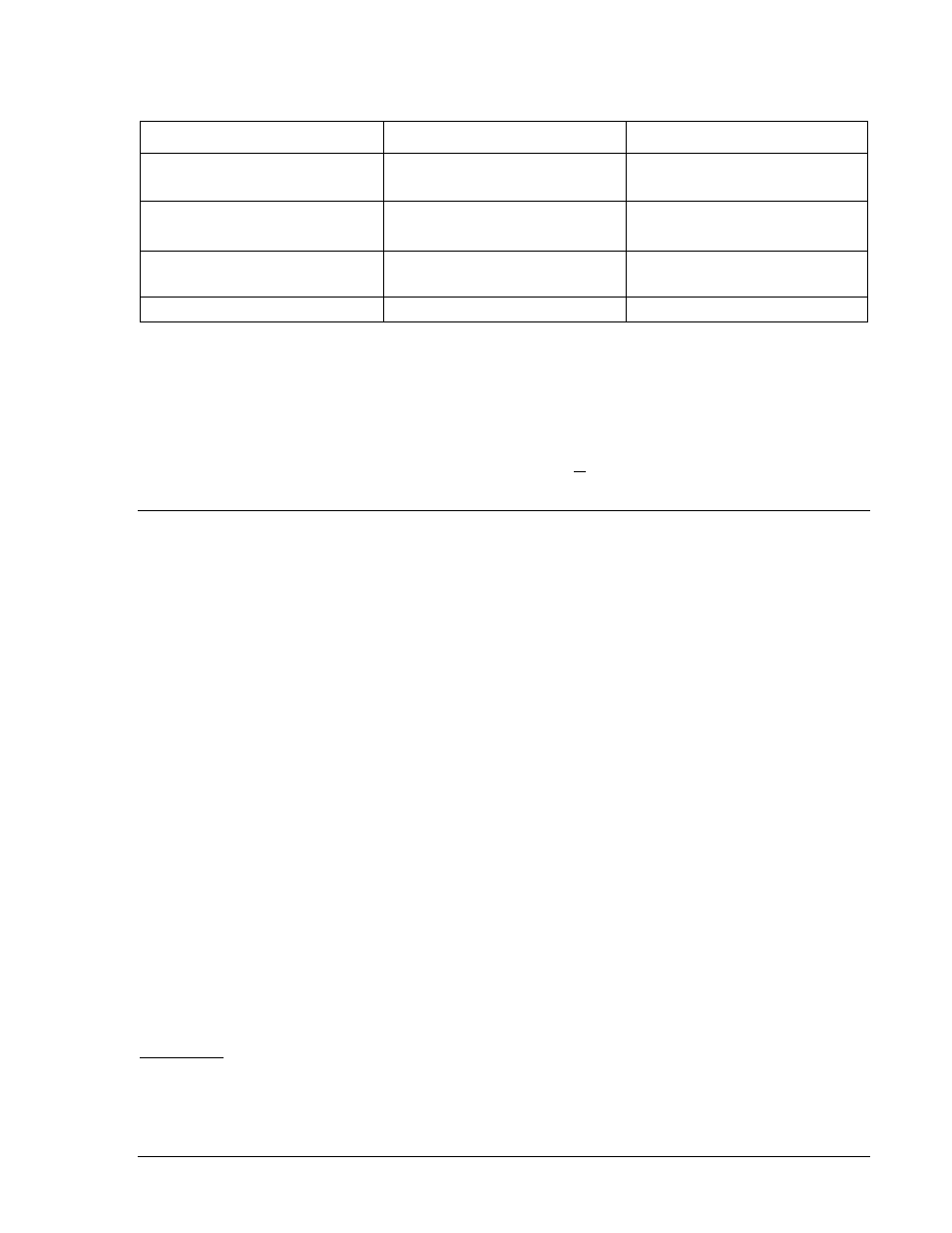
Table 6-2. Time and Date Format Settings
Parameter
Range
Default
Time Format
12 (12 hour format)
24 (24 hour format)
24
Date Format
m (mm-dd-yy)
d (dd-mm-yy)
M
Automatic Daylight Savings
0 (daylight saving time disabled)
1 (daylight saving time enabled)
0
Front Panel Back Light Delay
0 to 600 seconds
600
Reading and Setting the Clock
Clock information can be viewed and set at the front panel human-machine interface (HMI) and through
the communication ports using ASCII commands or BESTCOMS. Write access to reports is required to
set the clock at the HMI and communication ports. An alarm point is provided in the programmable alarms
to detect when the relay has powered up and the clock has not been set. Time and date information is
read and set at HMI Screen 4.6, through the communication ports using the RG-DATE and RG-TIME
ASCII commands, and through BESTCOMS by selecting the Communication pull-down menu and then
selecting Set Date and Time.
GENERAL STATUS REPORTING
BE1-700 relays have extensive capabilities for reporting relay status. This is important for determining the
health and status of the system for diagnostics and troubleshooting. Throughout this manual, reference is
made to the RG-STAT (report general, status) report and the appropriate HMI screens for determining the
status of various functions.
General Status Report
A General Status report is available through the communication ports using the RG-STAT command. This
report lists all of the information required to determine the status of the relay. An example of a typical
General Status report follows as well as a description of what each line represents. In the explanation of
each line, cross-references are made to the corresponding HMI screens that contain that data.
>RG-STAT
INPUT(1234) STATUS : 0000
OUTPUT(A12345) STATUS : 000000
CO-OUT(A12345) STATUS : LLLLLL
CO-43/143 STATUS : 00
CO-101(101SC) STATUS : AFTER CLOSE(1)
CO-GROUP STATUS : L
ACTIVE LOGIC STATUS : 700C-5051-A-BE
RECLOSER(79) STATUS : LOCKOUT
∗
LOGIC VAR(00-31) STATUS : 00000000 00000000 00000000 00010000
LOGIC VAR(32-63) STATUS : 00000000 00000000 00000000 00100010
LOGIC VAR(64-95) STATUS : 01000000 00000000 00000000 00000000
ACTIVE GROUP STATUS : 0
BREAKER(52) STATUS : CLOSED
DIAG/ALARM STATUS : 0 RELAY, 0 LOGIC, 0 MAJOR, 0 MINOR
∗ Recloser (79) is optional. See Style Chart in Section 1, General Information.
Input (1234)
This line reports the status of contact sensing inputs IN1, IN2, IN3, and IN4. Input information is available
at HMI Screen 1.5.1. “0” indicates a de-energized input and “1” indicates an energized input. See Section
3, Input and Output Functions, for more information about contact sensing input operation.
9376700990 Rev M
BE1-700 Reporting and Alarm Functions
6-3