Table 13-53. 27x and 59x/159x pickup settings -34, Table 13-54. uv inhibit for 27x (3, Harmonic vx input) pickup settings -34 – Basler Electric BE1-700 User Manual
Page 330: Table 13-53
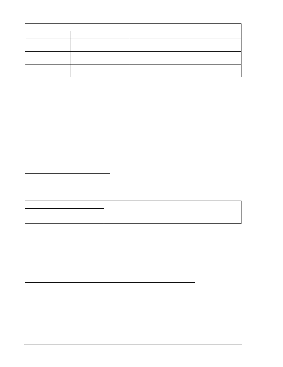
Table 13-53. 27X and 59X/159X Pickup Settings
Pickup and Time Delay Settings
Purpose
Undervoltage
Overvoltage
S0-27X=70,50ms,0
S0-59X/159X=90,50ms
Sets 27X PU at 70 V, 59X/159X at 90 V, TD at min,
UV Inhibit disabled.
S0-27X=60,50ms,0
S0-59X/159X=100,50ms
Sets 27X PU at 60 V, 59X/159X at 100 V, TD at
min, UV Inhibit disabled.
S0-27X=50,50ms,0
S0-59X159X=110,50ms
Sets 27X PU at 50 V, 59X/159X at 110 V, TD at
min, UV Inhibit disabled.
Step 3: Prepare to monitor the 27X and 59X/159X function operation. Operation can be verified by
monitoring OUT1.
Step 4: Connect and apply a single-phase, 80 Vac, 3
rd
harmonic voltage source to Terminals C17
(polarity) and C18 (non-polarity). Refer to Figure 12-4 for terminal locations.
Step 5: Slowly decrease the voltage until OUT1 closes. Pickup should occur within
±2 percent or 1 volt
of the pickup setting. Slowly increase the voltage until OUT1 opens. Dropout should occur
between 102% and 103% of the actual pickup value. Verify the 27-3 Bus target on the HMI.
Step 6: Continue to increase voltage until OUT1 closes. Pickup should occur within
±2 percent or 1 volt
of the pickup setting. Slowly reduce the voltage until OUT1 opens. Dropout should occur
between 97% and 98% of the actual pickup value.
Step 7: Verify the pickup and dropout accuracy of the middle and upper pickup settings listed in Table
13-53. Verify the 59-3 Bus target on the HMI.
Step 8: (Optional.) Repeat Steps 2 through 7 for Setting Group 1.
UV Inhibit for 27X (3
rd
Harmonic VX Input)
Step 1: Using Table 13-54 as a guide, transmit the setting commands to the relay.
Table 13-54. UV Inhibit for 27X (3
rd
Harmonic VX Input) Pickup Settings
Phase Inhibit Pickup Settings
Purpose
Undervoltage
S0-27X=96,50ms,50
Sets 27X PU at 96 V, Time Dial at minimum, UV Inhibit at 50V.
Step 2: Connect and apply a single-phase, 80 Vac, 3
rd
harmonic voltage source to Terminals C17
(polarity) and C18 (non-polarity). Refer to Figure 12-4 for terminal locations.
Step 3: Slowly decrease the voltage until OUT1 closes. Pickup should occur within
±2 percent or 1 volt
of the pickup setting. Continue to decrease the voltage until OUT1 opens. UV inhibit pickup
should occur within
±3 percent of 50V. Increase the voltage until OUT1 closes. UV inhibit
dropout should occur at
±5 percent of inhibit pickup.
Step 4: (Optional.) Repeat Steps 1 through 3 for Setting Group 1.
Auxiliary Undervoltage and Overvoltage Timing Verification (3
rd
Harmonic VX Input)
Step 1: Using Table 13-55 as a guide (same values as the fundamental test but at 3
rd
harmonic
frequency), transmit the first row of setting commands to the relay.
13-34
BE1-700 Testing and Maintenance
9376700990 Rev M