Basler Electric BE1-700 User Manual
Page 344
Command
Purpose
S0-162=400m,20s
Sets 162 delay at 400 milliseconds. Sets 162 dropout at 20 seconds.
EXIT;Y
Exit and save settings.
Step 2: Transmit the commands of Table 13-87 to the relay. These commands supply the 162 Timer
with a momentary initiate input by pulsing the 143 Switch from a FALSE state to a TRUE state
and then back to a FALSE state. You may view the state changes of the 143 Switch at Screen
1.5.4 of the front panel HMI.
Table 13-87. x62 Mode 2 Timer Initiate Commands
Command
Purpose
A=
Gains write access.
CS-143=P
Selects 143 for pulse F-T-F operation.
CO-143=P
Executes 143 pulse F-T-F operation.
CS-143=P
Selects 143 for pulse F-T-F operation.
CO-143=P
Executes 143 pulse F-T-F operation.
EXIT
Exit select and operate mode.
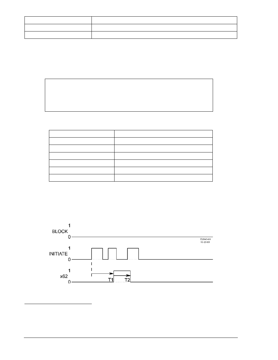
Step 3: Use the RS-LGC command to retrieve logic variable data from the SER. Verify that a 143
FALSE-TRUE-FALSE pulse action was logged and that approximately 400 milliseconds after
the initial 143 FALSE-TRUE-FALSE initiate signal action, the 162 Timer output went TRUE.
Then, approximately 20 seconds later, duration Timer T2 expired and the timer output went
FALSE despite a second 143 FALSE to TRUE initiate signal while the duration timer was active.
Figure 13-2 illustrates the timing relationship of the 143 Switch and x62 Timer.
Figure 13-2. Mode 2 and x62 Timer Relationship Example
Mode 3 - One-Shot Retriggerable
Step 1: Prepare the 62 Timer for Mode 3 testing by transmitting the commands in Table 13-88.
NOTE
The 143 Switch action is performed twice in this test. To illustrate the action of
the timer mode, the commands of Table 13-87 should be executed as quickly as
possible. Ideally, this test should be repeated within 20 seconds. If this is a
problem, try extending the dropout timer setting to 30 seconds.
13-48
BE1-700 Testing and Maintenance
9376700990 Rev M