Figure 7-6. bestlogic expression builder screen -7 – Basler Electric BE1-700 User Manual
Page 175
Logic equations are defined by logic variables, logic operators, and their position in an equation. The
available logic operators include AND (
∗), OR (+) and NOT (/). The NOT operator is applied to the
variable immediately following the symbol (/). For virtual output equations, OR logic can be applied to any
number of variables if no AND logic is used in the expression. Similarly, AND logic can be applied to any
number of variables if no OR logic is used. Any number of NOT operators may be used. For complex
expressions that use both AND and OR operators, OR logic is limited to four terms. Up to four AND terms
with any number of variables can be ORed together. When the relay is processing a complex expression,
it performs AND operations before performing OR operations.
Virtual and Hardware Outputs
A virtual output exists only as a logical state inside the relay. A hardware output is a physical relay contact
that can be used for protection or control. Each BE1-700 relay has five isolated, normally open (NO)
output contacts (OUT1 – OUT5) and one isolated, normally closed (NC) alarm output (OUTA). Output
contacts OUT1 through OUT5 are controlled by the status of the internal virtual logic signals VO1 through
VO5. If VO[n] becomes TRUE, then the corresponding output relay OUT[n] energizes and closes the NO
contacts. For the alarm output, if VOA becomes TRUE, the ALM output de-energizes and closes. More
information about input and output functions is provided in Section 3, Input and Output Functions.
Hardware outputs can also be controlled by the CO-OUT (control operate, output) command. The CO-
OUT command overrides control of logic outputs. Outputs may be pulsed or latched in a 0 or 1 state
independently from the state of the virtual output logic. More information about overriding control of logic
outputs is available in Section 3, Input and Output Functions.
BESTlogic Expression Builder
The BESTlogic Expression Builder is used to connect the inputs of the relay's function blocks, physical
inputs and outputs, and virtual outputs. Using the BESTlogic Expression Builder is analogous to
physically attaching wire between discrete relay terminals. The BESTlogic Expression Builder is opened
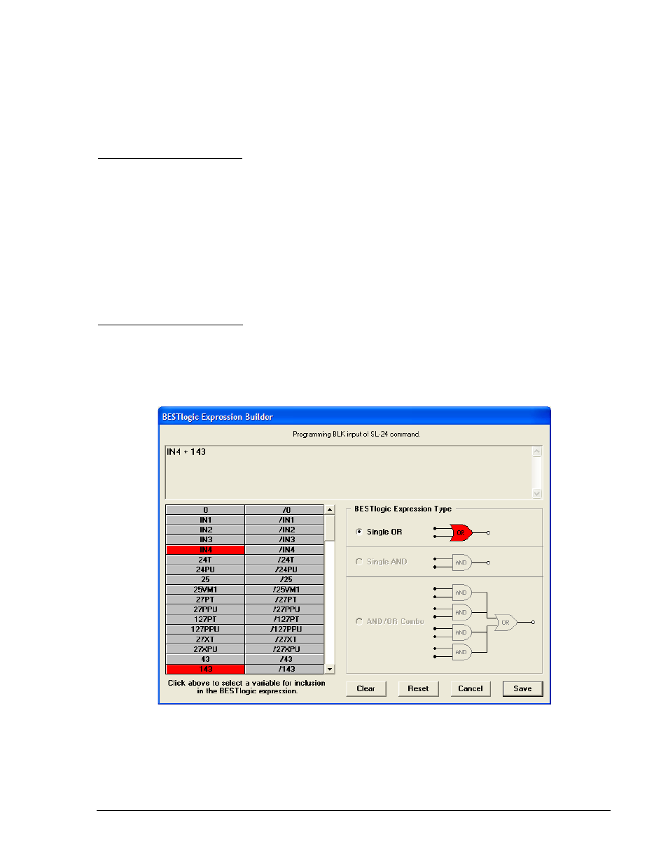
each time the input of a BESTlogic function block is selected. Figure 7-6 illustrates the BESTlogic
Expression Builder screen.
Figure 7-6. BESTlogic Expression Builder Screen
The BESTlogic Expression Builder provides a point and click interface that allows the selected input to be
easily connected using a single OR gate, single AND gate, or an AND/OR combination. The usable list of
inputs and outputs in the bottom left of the screen corresponds with the variable lists of Table 7-1 and
Table 7-2. Currently, the virtual outputs are the only functions that can use the single AND or AND/OR
combination BESTlogic Expression Type.
9376700990 Rev M
BE1-700 BESTlogic Programmable Logic
7-7