Configuration procedure – H3C Technologies H3C SecPath F1000-E User Manual
Page 102
77
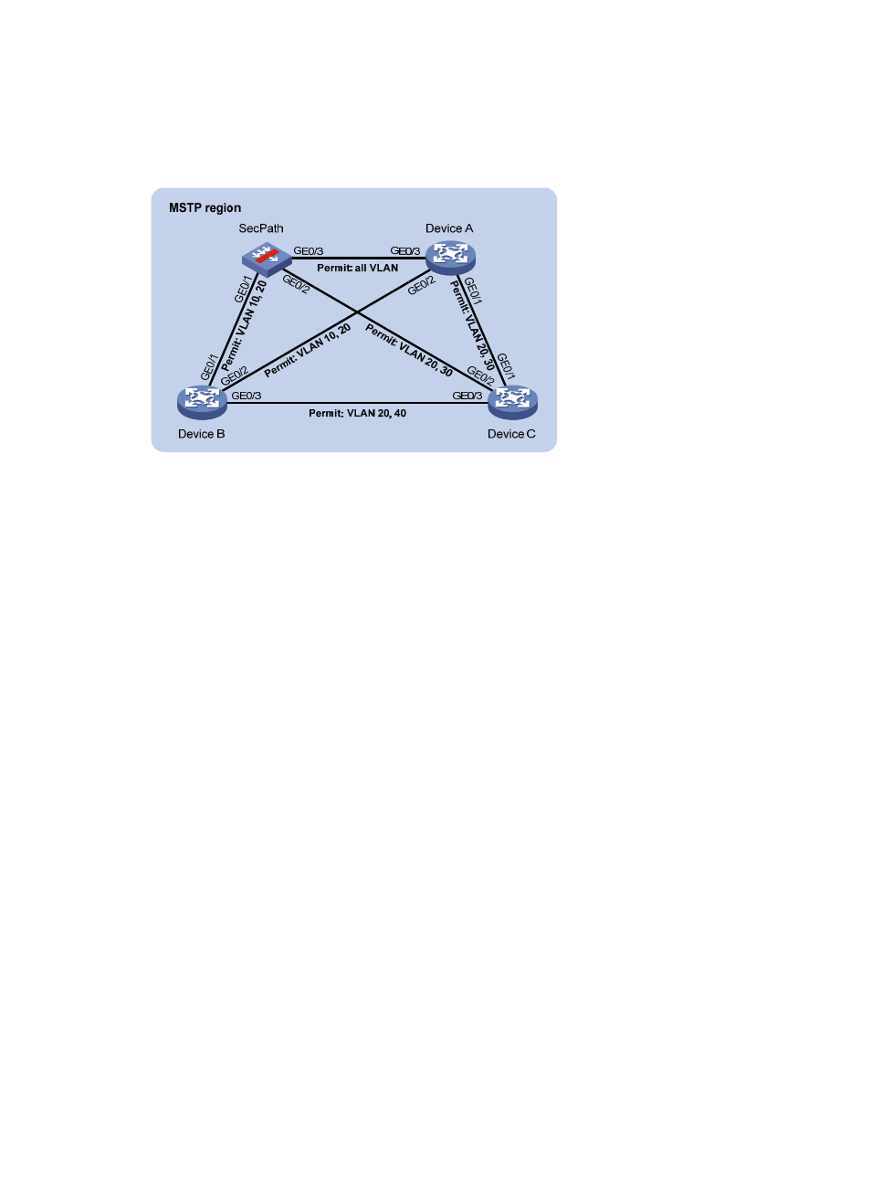
VLAN 10 and VLAN 30 are terminated on the distribution layer devices, and VLAN 40 is terminated on
the access layer devices, so the root bridges of MSTI 1 and MSTI 3 are SecPath and Device A respectively,
and the root bridge of MSTI 4 is Device B.
Figure 49 Network diagram
Configuration procedure
1.
Configure the VLANs and VLAN member ports. (Details not shown.)
Create VLAN 10, VLAN 20, and VLAN 30 on SecPath and Device A respectively, create VLAN 10,
VLAN 20, and VLAN 40 on Device B, and create VLAN 20, VLAN 30, and VLAN 40 on Device
C; configure the ports on these devices as hybrid ports and assign them to related VLANs;
configure the security zones to which the combinations of these ports and their permitted VLANs
belong.
2.
Configure SecPath:
# Enter MST region view, configure the MST region name as example, map VLAN 10, VLAN 30,
and VLAN 40 to MSTI 1, MSTI 3, and MSTI 4 respectively, and configure the revision level of the
MST region as 0.
{
Log in to Device A. Select Network > MSTP > Region from the navigation tree, click Modify, and
make the following configurations on the page shown in
.