H3C Technologies H3C SecPath F1000-E User Manual
Page 85
60
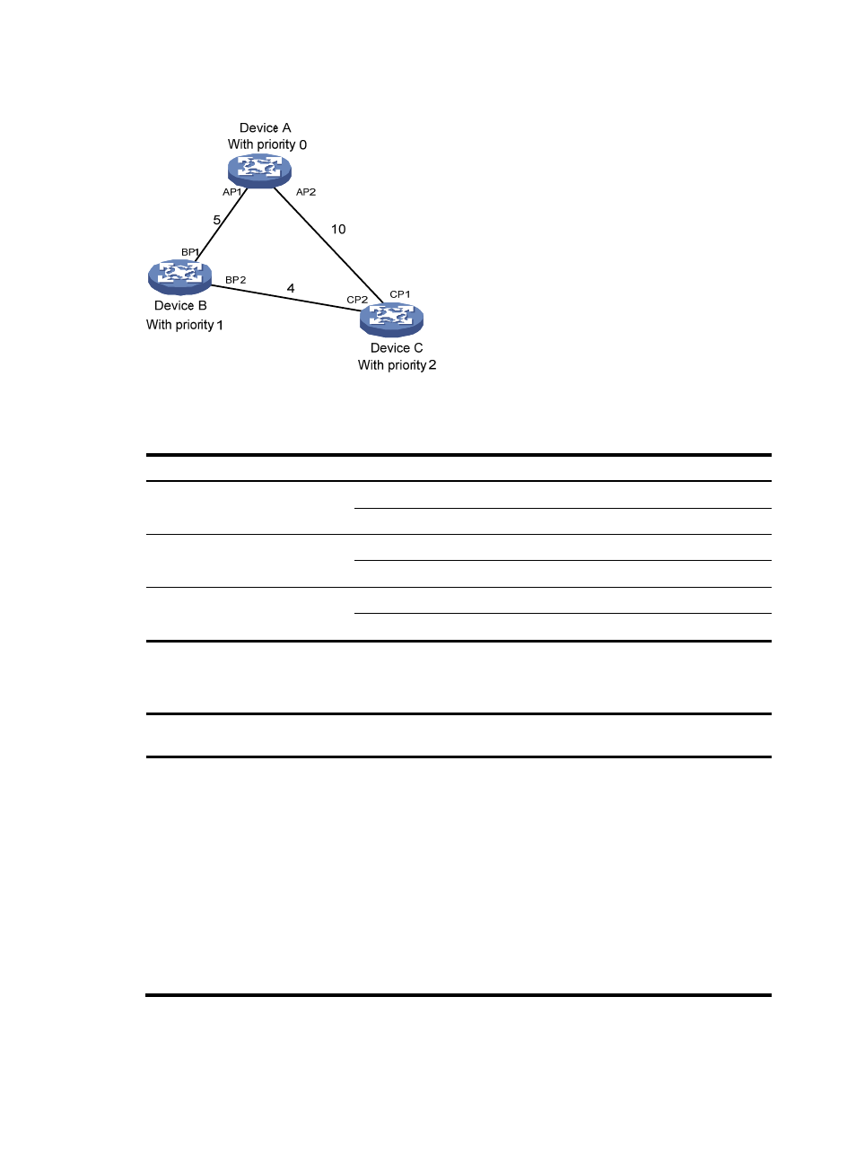
Figure 40 The STP algorithm
•
Initial state of each device
Table 12 Initial state of each device
Device
Port name
BPDU of port
Device A
AP1
{0, 0, 0, AP1}
AP2
{0, 0, 0, AP2}
Device B
BP1
{1, 0, 1, BP1}
BP2
{1, 0, 1, BP2}
Device C
CP1
{2, 0, 2, CP1}
CP2
{2, 0, 2, CP2}
•
Comparison process and result on each device
Table 13 Comparison process and result on each device
Device
Comparison process
BPDU of port after
comparison
Device A
•
Port AP1 receives the configuration BPDU of Device B {1, 0, 1,
BP1}. Device A finds that the configuration BPDU of the local
port {0, 0, 0, AP1} is superior to the received configuration
BPDU, and discards the received configuration BPDU.
•
Port AP2 receives the configuration BPDU of Device C {2, 0, 2,
CP1}. Device A finds that the BPDU of the local port {0, 0, 0,
AP2} is superior to the received configuration BPDU, and
discards the received configuration BPDU.
•
Device A finds that both the root bridge and designated bridge
in the configuration BPDUs of all its ports are itself, so it assumes
itself to be the root bridge. It does not make any change to the
configuration BPDU of each port, and starts sending out
configuration BPDUs periodically.
AP1: {0, 0, 0, AP1}
AP2: {0, 0, 0, AP2}