Configuration procedure, Figure 57 network diagram, Activate mst region configuration – H3C Technologies H3C SecPath F1000-E User Manual
Page 130: Enable the spanning tree feature globally
105
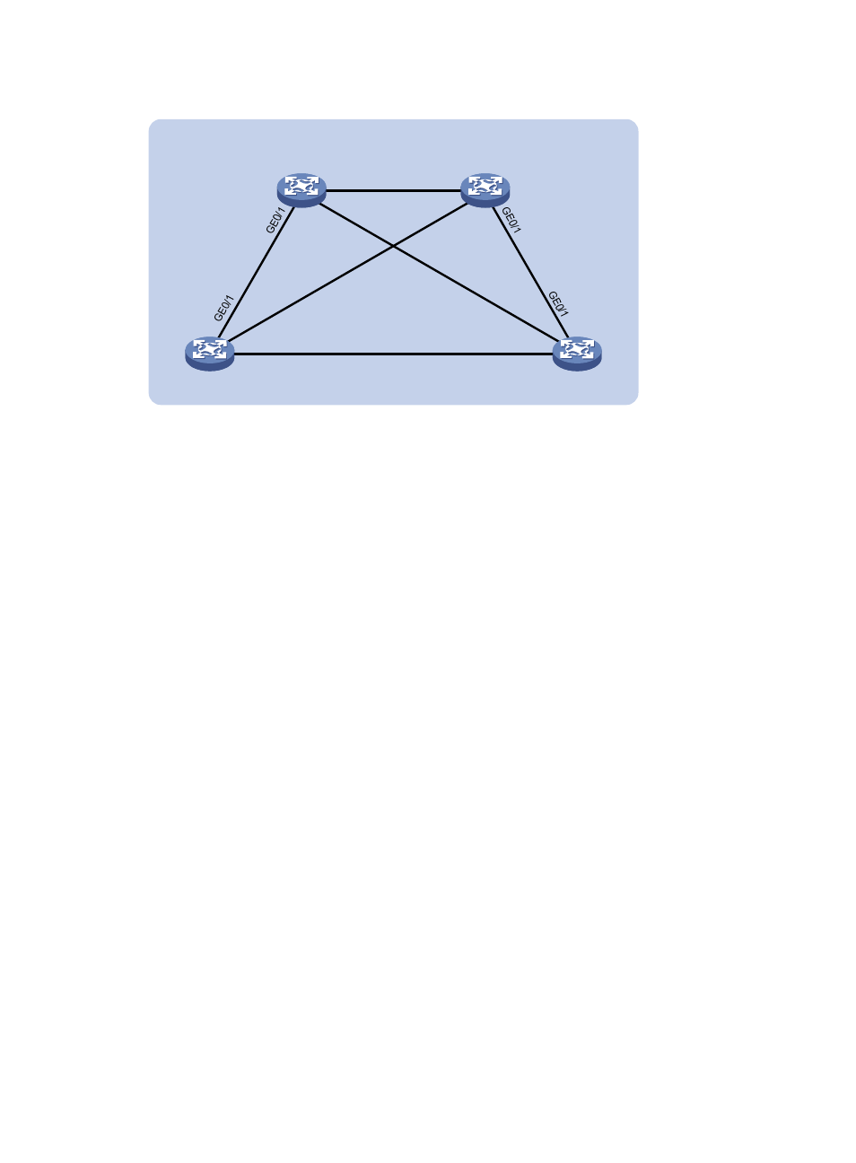
Figure 57 Network diagram
Configuration procedure
1.
Configure VLANs and VLAN member ports. (Details not shown.)
Create VLAN 10, VLAN 20, and VLAN 30 on Device A and Device B respectively, VLAN 10,
VLAN 20, and VLAN 40 on Device C, and VLAN 20, VLAN 30, and VLAN 40 on Device D.
Configure the ports on these devices as trunk ports and assign them to related VLANs.
2.
Configure Device A:
# Enter MST region view, configure the MST region name as example, map VLAN 10, VLAN 30,
and VLAN 40 to MSTI 1, MSTI 3, and MSTI 4 respectively, and configure the revision level of the
MST region as 0.
<DeviceA> system-view
[DeviceA] stp region-configuration
[DeviceA-mst-region] region-name example
[DeviceA-mst-region] instance 1 vlan 10
[DeviceA-mst-region] instance 3 vlan 30
[DeviceA-mst-region] instance 4 vlan 40
[DeviceA-mst-region] revision-level 0
# Activate MST region configuration.
[DeviceA-mst-region] active region-configuration
[DeviceA-mst-region] quit
# Specify the current device as the root bridge of MSTI 1.
[DeviceA] stp instance 1 root primary
# Enable the spanning tree feature globally.
[DeviceA] stp enable
3.
Configure Device B:
# Enter MST region view, configure the MST region name as example, map VLAN 10, VLAN 30,
and VLAN 40 to MSTI 1, MSTI 3, and MSTI 4 respectively, and configure the revision level of the
MST region as 0.
<DeviceB> system-view
[DeviceB] stp region-configuration
Permit: all VLANs
Per
mit:
VL
AN
s 2
0 a
nd 3
0
Pe
rm
it:
V
LA
Ns
10
an
d 2
0
Permit: VLANs 20 and 40
Permit: VLANs 20 and
30
Permit: VLANs 10 and
20
Device A
Device B
Device C
Device D
GE0/3
GE
0/2
GE0/3
GE
0/2
GE0/3
GE0/3
GE
0/2
GE
0/2
MST region