Configuration procedure – H3C Technologies H3C SecPath F1000-E User Manual
Page 689
664
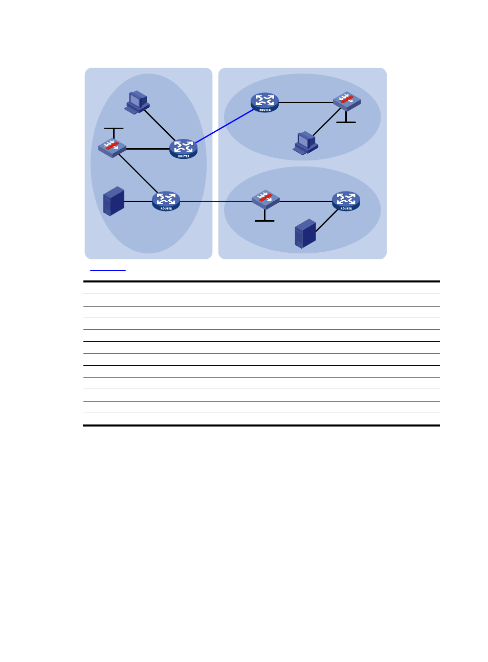
Figure 350 Network diagram
Device Interface
IP
address
Device
Interface
IP address
Source 1
-
192.168.1.100/24 SecPath B
GE0/1
10.110.5.1/24
Source 2
-
192.168.3.100/24
GE0/2
10.110.3.2/24
SecPath A
GE0/1
10.110.1.1/24
Loop0
2.2.2.2/32
GE0/2
10.110.2.1/24
Router
C
GE0/1
10.110.5.2/24
Loop0
1.1.1.1/32
GE0/2
192.168.3.1/24
Router A GE0/1 10.110.1.2/24
Router D
GE0/1
10.110.6.1/24
GE0/2
192.168.1.1/24
GE0/2
10.110.4.2/24
GE0/3
10.110.3.1/24
SecPath C
GE0/1
10.110.6.2/24
Router B
GE0/1
10.110.2.2/24
GE0/2
192.168.4.1/24
GE0/2
192.168.2.1/24
Loop0
3.3.3.3/32
GE0/3
10.110.4.1/24
Configuration procedure
1.
Configure IP addresses and unicast routing:
Configure the IP address and subnet mask for each interface as per
shown.)
Configure OSPF on routers and firewalls in each AS to make sure the network-layer in each AS is
interoperable and routing information among the routers and firewalls can be dynamically
updated. (Details not shown.)
2.
Enable IP multicast routing, enable PIM-SM and IGMP, and configure a PIM-SM domain border:
# Enable IP multicast routing on Router B, enable PIM-SM on each interface, and enable IGMP on
the host-side interface GigabitEthernet 0/2.
<RouterB> system-view
[RouterB] multicast routing-enable
[RouterB] interface GigabitEthernet 0/1
[RouterB-GigabitEthernet0/1] pim sm
GE0/3
GE
0/2
Router A
SecPath A
Source 1
AS 100
PIM-SM 1
PIM-SM 3
PIM-SM 2
Loop0
SecPath B
Router C
Router D
SecPath C
Source 2
GE0/2
GE0/1
GE0/2
GE0/1
GE0/1
Loop0
Receiver
Receiver
Loop0
BGP peers
GE0/
1
GE0/1
GE0/1
GE0/2
GE0/2
AS 200
GE
0/3
GE0/1
GE0
/2
GE0/2
Router B