Configuring the switch, Configuring the secpath – H3C Technologies H3C SecPath F1000-E User Manual
Page 285
260
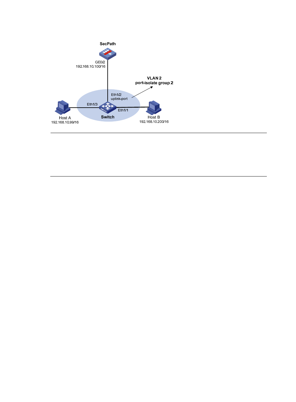
Figure 166 Network diagram
NOTE:
In this configuration example, suppose all traffic between the hosts is blocked, so you need to configure
local proxy ARP on GigabitEthernet 0/2 of the SecPath to enable communication between Host A and
Host B. If the two ports (Ethernet 1/3 and Ethernet 1/1) on the switch are isolated only at Layer 2, you can
enable communication between the two hosts by configuring local proxy ARP on VLAN-interface 2 of the
switch.
Configuring the switch
# Add Ethernet 1/3, Ethernet 1/1 and Ethernet 1/2 to VLAN 2. Configure port isolation on Host A and
Host B.
<Switch> system-view
[Switch] port-isolate group 2
[Switch] vlan 2
[Switch-vlan2] port ethernet 1/3
[Switch-vlan2] port ethernet 1/1
[Switch-vlan2] port ethernet 1/2
[Switch-vlan2] quit
[Switch] interface ethernet 1/3
[Switch-Ethernet1/3] port-isolate enable group 2
[Switch-Ethernet1/3] interface ethernet 1/1
[Switch-Ethernet1/1] port-isolate enable group 2
[Switch-Ethernet1/1] interface ethernet 1/2
[Switch-Ethernet1/2] port-isolate uplink-port group 2
Configuring the SecPath
# Specify the IP address of GigabitEthernet 0/2.
<SecPath> system-view
[SecPath] interface GigabitEthernet 0/2
[SecPath-GigabitEthernet0/2] ip address 192.168.10.100 255.255.0.0
The ping operation from Host A to Host B is unsuccessful because they are isolated at Layer 2 and Layer
3.
# Configure local proxy ARP to allow communication between Host A and Host B at Layer 3.
[SecPath-GigabitEthernet0/2] local-proxy-arp enable