Configuring ospf virtual links at the cli, Network requirements, Configuration procedure – H3C Technologies H3C SecPath F1000-E User Manual
Page 457
432
Interfaces
Area: 0.0.0.0
IP Address Type State Cost Pri DR BDR
192.168.1.2 Broadcast DROther 1 0 192.168.1.1 192.168.1.3
The interface state DROther means the interface is not the DR/BDR.
Configuring OSPF virtual links at the CLI
Network requirements
NOTE:
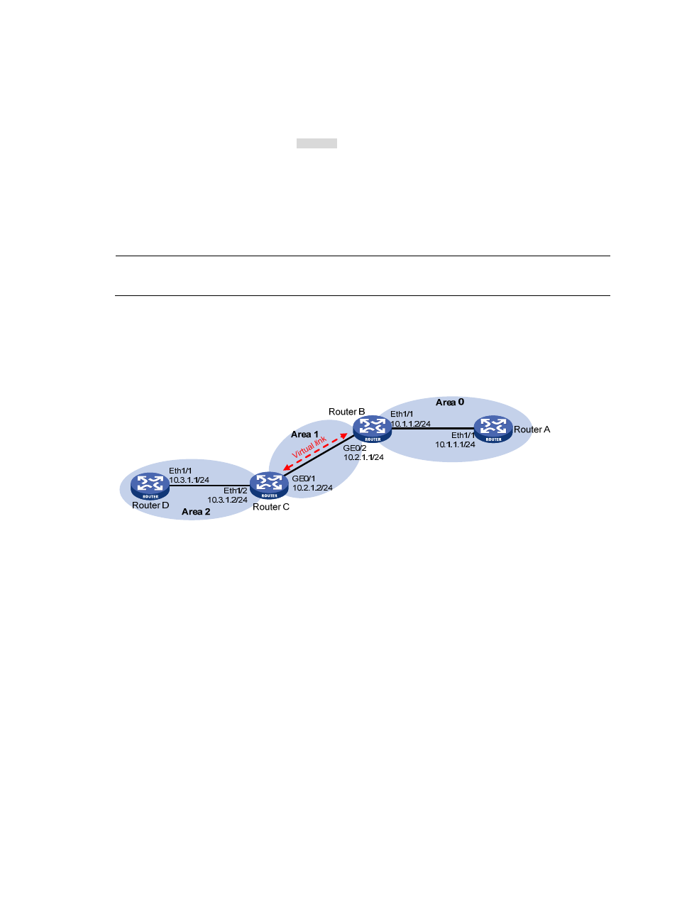
In this configuration example, either Router B or Router C is the SecPath firewall.
, Area 2 has no direct connection to Area 0, the backbone, and Area 1 acts as the Transit
Area to connect Area 2 to Area 0 via a virtual link between Router B and Router C.
After configuration, Router B can learn routes to Area 2.
Figure 273 Network diagram
Configuration procedure
1.
Configure IP addresses for interfaces. (Details not shown)
2.
Configure OSPF basic functions:
# Configure Router A.
<RouterA> system-view
[RouterA] ospf 1 router-id 1.1.1.1
[RouterA-ospf-1] area 0
[RouterA-ospf-1-area-0.0.0.0] network 10.1.1.0 0.0.0.255
[RouterA-ospf-1-area-0.0.0.0] quit
# Configure Router B.
<RouterB> system-view
[RouterB] ospf 1 router-id 2.2.2.2
[RouterB-ospf-1] area 0
[RouterB-ospf-1-area-0.0.0.0] network 10.1.1.0 0.0.0.255
[RouterB-ospf-1-area-0.0.0.0] quit
[RouterB-ospf-1] area 1
[RouterB–ospf-1-area-0.0.0.1] network 10.2.1.0 0.0.0.255
[RouterB–ospf-1-area-0.0.0.1] quit