Configuration procedure – H3C Technologies H3C SecPath F1000-E User Manual
Page 298
273
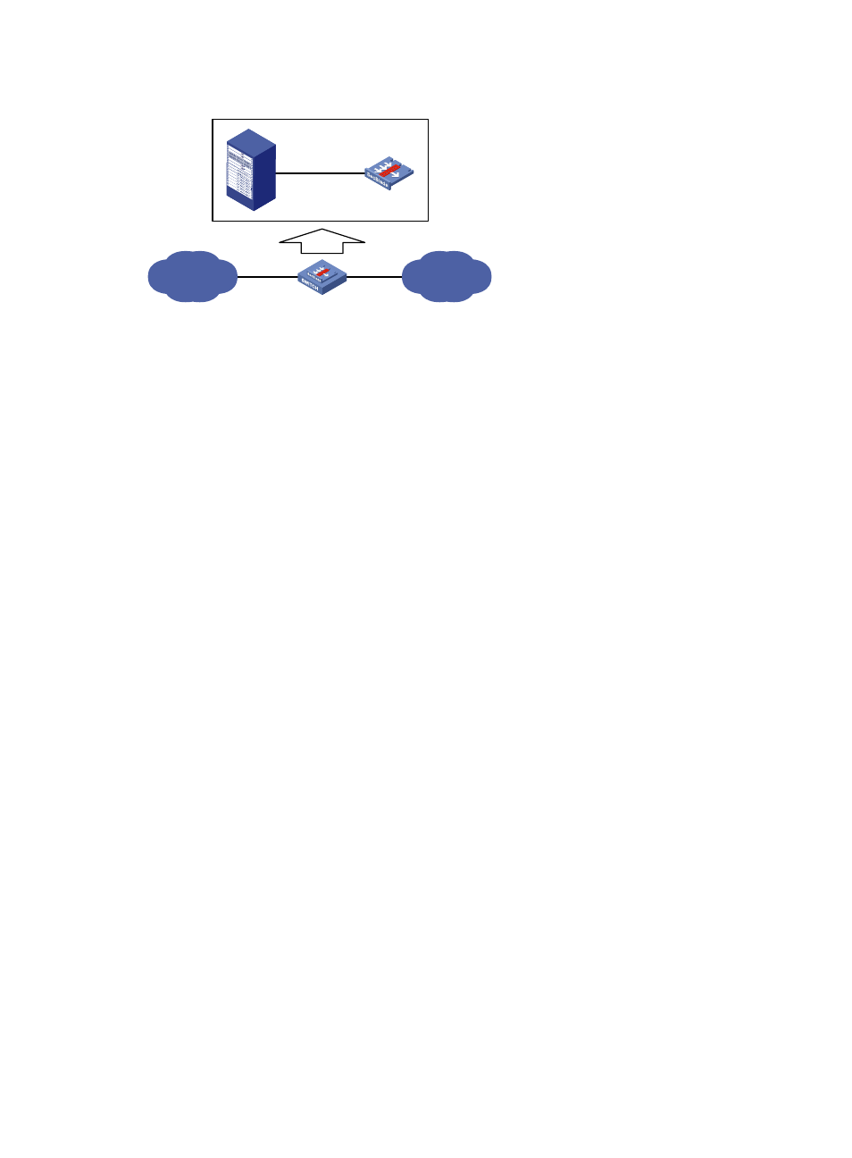
Figure 170 Network diagram for inter-VLAN Layer 3 forwarding
Configuration procedure
1.
Configure the ports on the switch.
# Create VLAN 102 and VLAN 103. Assign GigabitEthernet 3/0/1 to VLAN 102 and GigabitEthernet
3/0/2 to VLAN 103.
<Sysname> system-view
[Sysname] vlan 102
[Sysname-vlan102] port GigabitEthernet 3/0/1
[Sysname-vlan102] vlan 103
[Sysname-vlan103] port GigabitEthernet 3/0/2
[Sysname-vlan103] quit
# Configure the link type of ten-GigabitEthernet 2/0/1 as trunk. Assign the port to VLAN 102 and VLAN
103.
[Sysname] interface Ten-GigabitEthernet 2/0/1
[Sysname-Ten-GigabitEthernet2/0/1] port link-type trunk
[Sysname-Ten-GigabitEthernet2/0/1] port trunk permit vlan 102 103
2.
Configure the firewall card.
# Create VLAN 102 and VLAN 103.
<Sysname> system-view
[sysname] vlan 102 to 103
# Configure the operating mode of ten-GigabitEthernet 0/0 as Layer 2.
[Sysname] interface Ten-GigabitEthernet 0/0
[Sysname-Ten-GigabitEthernet0/0] port link-mode bridge
[Sysname-Ten-GigabitEthernet0/0] port link-type trunk
[Sysname-Ten-GigabitEthernet0/0] port trunk permit vlan 102 to 103
# Create two VLAN interfaces for ten-GigabitEthernet 0/0, VLAN-interface 102 and VLAN-interface
103.
[Sysname-Ten-GigabitEthernet0/0] interface vlan-interface 102
[Sysname-Vlan-interface102] ip address 102.0.0.3 24
[Sysname-Vlan-interface102] interface vlan-interface 103
[Sysname-Vlan-interface103] ip address 103.0.0.3 24
# Add ten-GigabitEthernet 0/0 and VLAN-interface 102 to the security zone Trust.
IP network
IP network
GE3/0/1
GE3/0/2
XGE2/0/1
XGE0/0