Network requirements, Configuring the switch – H3C Technologies H3C SecPath F1000-E User Manual
Page 286
261
The ping operation from Host A to Host B is successful after the configuration.
Local proxy ARP configuration example in isolate-user-VLAN
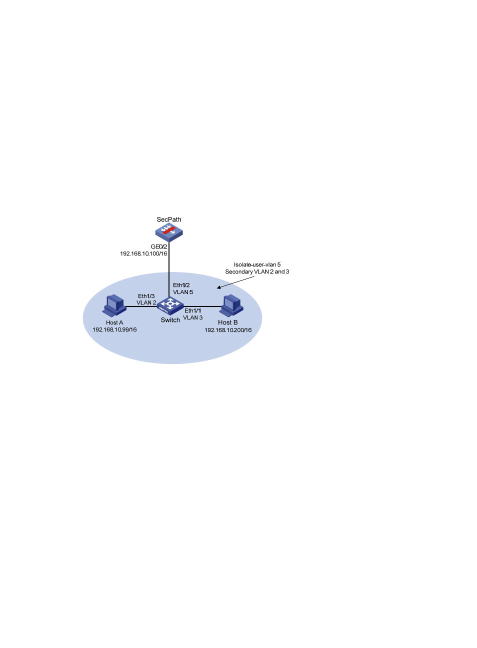
Network requirements
, the switch is attached to the SecPath. VLAN 5 on the switch is an
isolate-user-VLAN, which includes uplink port Ethernet 1/2 and two secondary VLANs, VLAN 2 and
VLAN 3. Ethernet 1/3 belongs to VLAN 2, and Ethernet 1/1 belongs to VLAN 3. Host A belongs to
VLAN 2 and connects to Ethernet 1/3 of the switch. Host B belongs to VLAN 3 and connects to Ethernet
1/1 of the switch.
As Host A and Host B belong to different secondary VLANs, they are isolated at Layer 2. Configure local
proxy ARP on the SecPath to implement Layer 3 communication between Host A and Host B.
Figure 167 Network diagram
Configuring the switch
# Create VLAN 2, VLAN 3, and VLAN 5 on the switch. Add Ethernet 1/3 to VLAN 2, Ethernet 1/1 to
VLAN 3, and Ethernet 1/2 to VLAN 5. Configure VLAN 5 as the isolate-user-VLAN, and VLAN 2 and
VLAN 3 as secondary VLANs. Configure the mappings between isolate-user-VLAN and the secondary
VLANs.
<Switch> system-view
[Switch] vlan 2
[Switch-vlan2] port ethernet 1/3
[Switch-vlan2] quit
[Switch] vlan 3
[Switch-vlan3] port ethernet 1/1
[Switch-vlan3] quit
[Switch] vlan 5
[Switch-vlan5] port ethernet 1/2
[Switch-vlan5] isolate-user-vlan enable
[Switch-vlan5] quit
[Switch] isolate-user-vlan 5 secondary 2 3