Configuration procedure, Network requirements – H3C Technologies H3C SecPath F1000-E User Manual
Page 284
259
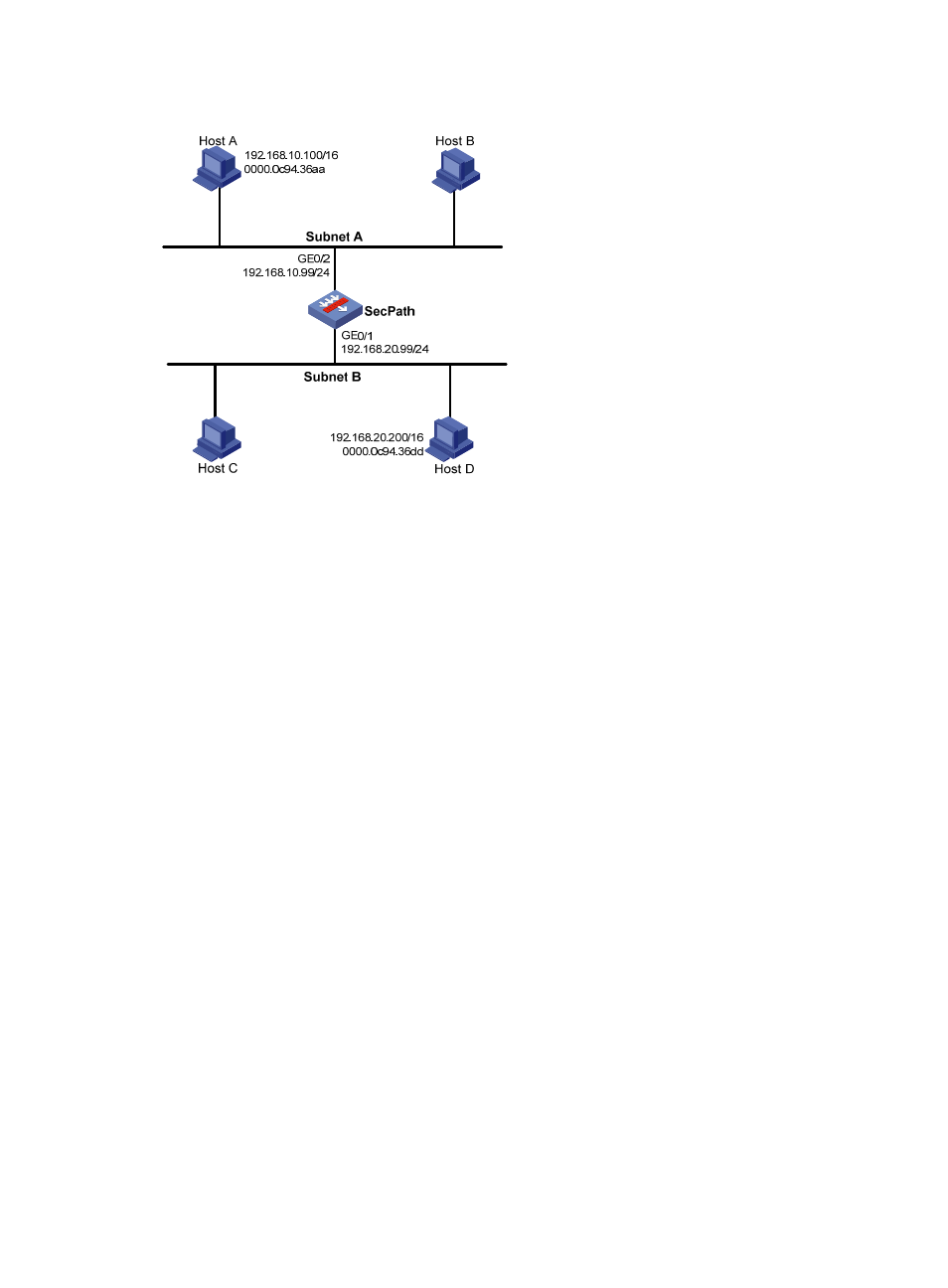
Figure 165 Network diagram
Configuration procedure
# Specify the IP address of interface GigabitEthernet 0/2.
<SecPath> system-view
[SecPath] interface GigabitEthernet 0/2
[SecPath-GigabitEthernet0/2] ip address 192.168.10.99 255.255.255.0
# Enable proxy ARP on interface GigabitEthernet 0/2.
[SecPath-GigabitEthernet0/2] proxy-arp enable
[SecPath-GigabitEthernet0/2] quit
# Specify the IP address of interface GigabitEthernet 0/1.
[SecPath] interface GigabitEthernet 0/1
[SecPath-GigabitEthernet0/1] ip address 192.168.20.99 255.255.255.0
# Enable proxy ARP on interface GigabitEthernet 0/1.
[SecPath-GigabitEthernet0/1] proxy-arp enable
[SecPath-GigabitEthernet0/1] quit
After completing preceding configurations, use the ping command to verify the connectivity between
Host A and Host D.
Local proxy ARP configuration example in case of port isolation
Network requirements
As shown in
, Host A and Host B belong to the same VLAN, and connect to the switch via
Ethernet 1/3 and Ethernet 1/1 respectively. The switch connects to the SecPath via Ethernet 1/2.
Configure port isolation on Ethernet 1/3 and Ethernet 1/1 of the switch to isolate Host A from Host B at
Layer 2. Enable local proxy ARP on the SecPath to allow communication between Host A and Host B at
Layer 3.