4 start-up flowcharts – Yaskawa L1000E AC Drive Technical Manual for CIMR-LE Models for Elevator Applications User Manual
Page 102
4.4 Start-Up Flowcharts
102
YASKAWA ELECTRIC SIEP YAIL1E 01A YASKAWA AC Drive L1000E Technical Manual
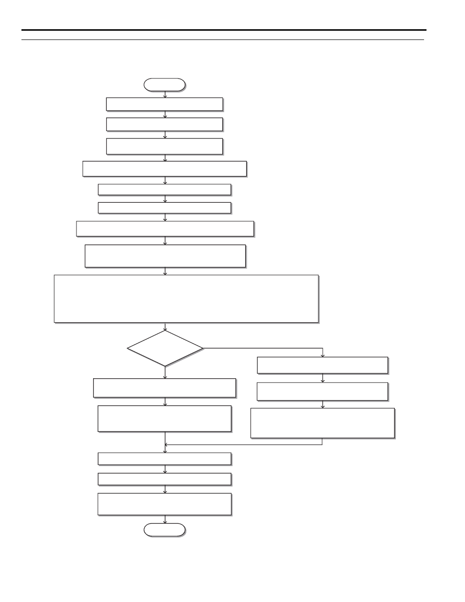
◆ Flowchart A: Installation, Wiring, Basic Setup for Motor and Elevator
The flowchart below covers the basic procedure required to install the drive, motor, and elevator.
Figure 4.11
Figure 4.12 Installation, Wiring, Basic Setup for Motor and Elevator
Note: Set parameter H5-11 to 1 when setting parameters using MEMOBUS/Modbus communications.
For control modes below, refer to
• V/f Control
• Open Loop Vector Control
• Closed Loop Vector Control
For Closed Loop Vector for PM, refer to
START
Install the drive as explained in
Wire the drive as explained in
Check the PG encoder power supply selection.
(Closed Loop Vector Control only -CLV)
Apply main power to the drive.
Adhere to safety messages concerning application of power.
Perform Auto-Tuning for motor parameters and the PG encoder offset.
Determine the
source of the speed
reference.
Analog Input
Digital operator (b1-01 = 0)
(Speed selection by digital inputs)
Assign functions to the analog/digital I/O terminals using
parameters H1-
, H2-
, H3-
, and H4-
.
Set up:
• Acceleration/deceleration ramp (C1-
)
• Jerk settings (C2-
)
Perform a test run.
Fine-tuning
• Adjust settings for the brake sequence (S1-
) .
• Adjust speed control loop (C5-
) etc.
FINISH
Set up:
• Preset speed references (d1-
)
• Acceleration/deceleration ramp (C1-
)
• Jerk settings (C2-
)
Assign functions to the digital I/O terminals using
parameters H1-
and H2-
.
Set the Speed Reference Selection mode
parameter d1-18.
Set the Unit Length in parameter o1-12.
Set up o1-20 to o1-22 and then select the display units for speed,
acceleration and deceleration ramp and jerk settings in o1-03.
Set up the Inspection Operation sequence.
Set up the PG encoder feedback in F1-
parameters when using a
Closed Loop Vector Control and check the PG encoder rotation direction.
Select the control mode in parameter A1-02.
Check the motor rotation direction.
Flowchart B: Auto-Tuning for Induction Motors on page 106
Flowchart C: Auto-Tuning for PM Motors on page 107
.
Mechanical Installation on page 40