9 n: special adjustments, N1: hunting prevention, N2: speed feedback detection control (afr) tuning – Yaskawa L1000E AC Drive Technical Manual for CIMR-LE Models for Elevator Applications User Manual
Page 232: N5: inertia compensation, N1-08: leakage current vibration control selection, N2-01: speed feedback detection control (afr) gain
232
YASKAWA ELECTRIC SIEP YAIL1E 01A YASKAWA AC Drive L1000E Technical Manual
5.9 n: Special Adjustments
5.9 n: Special Adjustments
These parameters handle a variety of specialized adjustments and functions, including AFR Control, resistance between
motor lines, PM motor control functions, and current detection adjustments.
◆ n1: Hunting Prevention
■
n1-08: Leakage Current Vibration Control Selection
Selects the method of Leakage-Current Vibration Control. Parameter does not typically require adjustment.
Setting 0: Method 1
Setting 1: Method 2
◆ n2: Speed Feedback Detection Control (AFR) Tuning
These parameters are used to achieve speed stability when a load is suddenly applied or removed.
Note: Properly set all motor parameters or perform Auto-Tuning before making changes to the AFR parameters.
■
n2-01: Speed Feedback Detection Control (AFR) Gain
Sets the internal speed feedback detection control gain in the AFR.
Although this parameter rarely needs to be changed, it may require adjustment in the following situations:
• If hunting occurs, increase the setting value in steps of 0.05 while checking the response.
• If response is low, decrease the setting value in steps of 0.05 while checking the response.
■
n2-02, n2-03: Speed Feedback Detection Control (AFR) Time Constant 1, 2
Parameter n2-02 sets the time constant normally used by AFR.
Parameter n2-03 sets the time constant during regenerative operation.
Note: Setting parameter n2-02 higher than n2-03 will trigger an oPE08 error.
Although these parameters rarely need to be changed, they may require adjustment in the following situations:
• If hunting occurs, increase n2-02. If response is low, decrease it.
• Increase n2-03 if overvoltage occurs with high inertia loads at the end of acceleration or with sudden load changes.
• If setting n2-02 to a higher value, also increase C4-02 (Torque Compensation Delay Time Constant 1) proportionally.
◆ n5: Inertia Compensation
Enabling Inertia Compensation improves the responsiveness of the drive to speed reference changes in applications where
a high speed control proportional gain setting (C5-01, C5-03, C5-13) would lead to problems with overshoot, undershoot,
or oscillation.
gives an example of overshoot reduction by Inertia Compensation. Parameters related to this
function and the function principle are illustrated in
. Inertia Compensation can only be used in Closed Loop
Vector Control for induction or PM motors (A1-02 = 3 or 7).
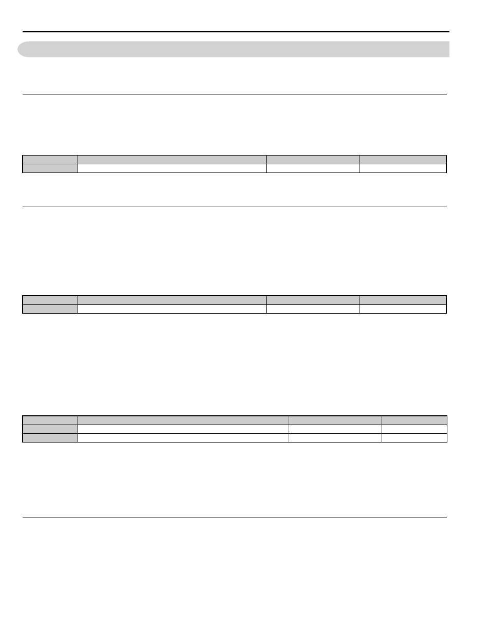
No.
Parameter Name
Setting Range
Default
n1-08
Leakage Current Vibration Control Selection
0, 1
0
No.
Parameter Name
Setting Range
Default
n2-01
Speed Feedback Detection Control (AFR) Gain
0.00 to 10.00
1.00
No.
Parameter Name
Setting Range
Default
n2-02
Speed Feedback Detection Control (AFR) Time Constant 1
0 to 2000 ms
50 ms
n2-03
Speed Feedback Detection Control (AFR) Time Constant 2
0 to 2000 ms
750 ms