4 alarm detection – Yaskawa L1000E AC Drive Technical Manual for CIMR-LE Models for Elevator Applications User Manual
Page 290
6.4 Alarm Detection
290
YASKAWA ELECTRIC SIEP YAIL1E 01A YASKAWA AC Drive L1000E Technical Manual
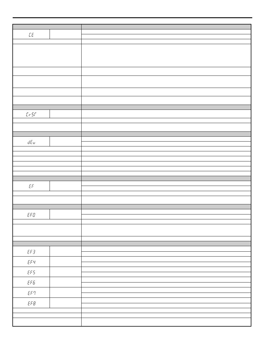
Digital Operator Display
Minor Fault Name
CE
MEMOBUS/Modbus Communication Error
Control data was not received correctly for two seconds.
Cause
Possible Solutions
A data error occurred due to noise.
• Check options available to minimize the effects of noise.
• Take steps to counteract noise in the control circuit wiring, main circuit lines, and ground wiring.
• Reduce noise on the controller side.
• Use surge absorbers for the magnetic contactors or other components that may be causing the disturbance.
• Use only recommended shielded line. Ground the shield on the controller side or on the drive input power side.
• Separate all wiring for comm. devices from drive input power lines. Install an EMC noise filter to the drive input power supply.
Communication protocol is incompatible.
• Check the H5 parameter settings as well as the protocol setting in the controller.
• Ensure settings are compatible.
The Communication Fault Detection Time (H5-09)
is set shorter than the time required for a
communication cycle to take place.
• Check the PLC.
• Change the software settings in the PLC.
• Set a longer Communication Fault Detection Time (H5-09).
Incompatible PLC software settings or there is a
hardware problem.
• Check the PLC.
• Remove the cause of the error on the controller side.
Communications cable is disconnected or damaged.
• Check the connector to make sure the cable has a signal.
• Replace the communications cable.
Digital Operator Display
Minor Fault Name
CrST
Cannot Reset
Cause
Possible Solutions
A fault reset command was entered while the Up/
Down command was still present.
• Ensure that a Up/Down command cannot be entered from the external terminals or option card during fault reset.
• Turn off the Up/Down command.
Digital Operator Display
Minor Fault Name
dEv
Speed Deviation (when using a PG option card)
The deviation between the speed reference and speed feedback is greater than the setting in F1-10 for longer than the time in F1-11.
Cause
Possible Solutions
Load is too heavy
Reduce the load.
Accel/decel ramp is too short.
Increase the acceleration and deceleration times (C1-01 through C1-08).
The load is locked up.
Check the machine.
Parameter settings are inappropriate.
Check the settings of parameters F1-10 and F1-11.
The motor brake is not applied.
Ensure the motor brake operates properly with a brake control command from the drive.
Digital Operator Display
Minor Fault Name
EF
Up/Down Command Error
Both forward run and reverse run closed simultaneously for over 0.5 s.
Cause
Possible Solutions
Sequence error
Check the forward and reverse command sequence and correct the problem.
Note: When minor fault EF detected, motor ramps to stop.
Digital Operator Display
Minor Fault Name
EF0
Option Card External Fault
An external fault condition is present.
Cause
Possible Solutions
An external fault was received from the PLC with
F6-03 = 3 (causing the drive to continue running
when an external fault occurs).
• Remove the cause of the external fault.
• Remove the external fault input from the PLC.
There is a problem with the PLC program.
Check the PLC program and correct problems.
Digital Operator Display
Minor Fault Name
EF3
External fault (input terminal S3)
External fault at multi-function input terminal S3.
EF4
External fault (input terminal S4)
External fault at multi-function input terminal S4.
EF5
External fault (input terminal S5)
External fault at multi-function input terminal S5.
EF6
External fault (input terminal S6)
External fault at multi-function input terminal S6.
EF7
External fault (input terminal S7)
External fault at multi-function input terminal S7.
EF8
External fault (input terminal S8)
External fault at multi-function input terminal S8.
Cause
Possible Solutions
An external device has tripped an alarm function.
Remove the cause of the external fault and reset the multi-function input value.
Wiring is incorrect.
• Ensure the signal lines have been connected properly to the terminals assigned for external fault detection (H1- = 2C to 2F).
• Reconnect the signal line.