S5: short floor operation, S4-07: ups power, S4-08: ups operation speed limit selection – Yaskawa L1000E AC Drive Technical Manual for CIMR-LE Models for Elevator Applications User Manual
Page 256: S4-12: dc bus voltage during rescue operation, Short floor function, 11 s: elevator parameters, Sets the capacity of the ups, Sets the dc bus voltage during rescue operation
5.11 S: Elevator Parameters
256
YASKAWA ELECTRIC SIEP YAIL1E 01A YASKAWA AC Drive L1000E Technical Manual
■
S4-07: UPS Power
Sets the capacity of the UPS.
■
S4-08: UPS Operation Speed Limit Selection
Determines how a speed limit should be applied to the Rescue Operation speed (d1-25) when operating from a UPS. The
drive calculates the appropriate speed limit based on the UPS capacity set in S4-07. This speed limit helps prevent voltage
saturation and motor stall during Rescue Operation.
Setting 0: Disabled
Setting 1: Enabled until Light Load Direction Search is complete
Setting 2: Enabled until stop
■
S4-12: DC Bus Voltage during Rescue Operation
Sets the DC bus voltage during Rescue Operation.
■
S4-13: Rescue Operation Power Supply Deterioration Detection Level
Determines at which level of backup power supply deterioration a PF5 fault is triggered. The following conditions will
trigger PF5:
• During Rescue Operation, DC bus voltage < [S4-12
× (S4-13 - 10%)]
• 100 ms after Rescue Operation has been triggered, the DC bus voltage does not rise above S4-12
× S4-13 before the
motor starts
■
S4-15: Speed Reference Selection at Rescue Operation
Selects the speed reference used for Rescue Operation.
Setting 0: The setting of parameter d1-25 is used as speed reference for Rescue Operation
Setting 1: The speed selected by digital inputs is used as speed reference
◆ S5: Short Floor Operation
■
Short Floor Function
Short Floor automatically adjusts the speed in order to reduce the leveling time if leveling speed was activated before the
selected speed was reached. Short Floor is enabled setting S5-01 = 1. The drive calculates the distance to decelerate from
rated speed to the leveling speed, then controls the stop so that the stopping time is shortened. In
below, area
S indicates the distance for a stop from nominal speed.
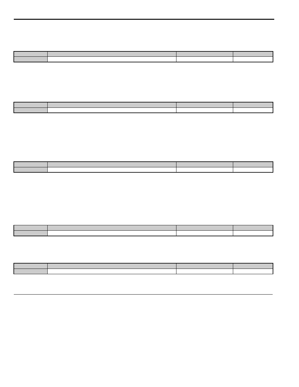
No.
Parameter Name
Setting Range
Default
S4-07
UPS Power
0.0 to 100.0 kVA
0.0 kVA
No.
Parameter Name
Setting Range
Default
S4-08
UPS Operation Speed Limit Selection
0 to 2
2
No.
Parameter Name
Setting Range
Default
S4-12
DC Bus Voltage during Rescue Operation
0 to 800 V
0 V
No.
Parameter Name
Setting Range
Default
S4-13
Rescue Operation Power Supply Deterioration Detection Level
10 to 100%
80%
No.
Parameter Name
Setting Range
Default
S4-15
Speed Reference Selection for Rescue Operation
0, 1
0