Yaskawa L1000E AC Drive Technical Manual for CIMR-LE Models for Elevator Applications User Manual
Page 128
4.6 Setup Procedure for Elevator Applications
128
YASKAWA ELECTRIC SIEP YAIL1E 01A YASKAWA AC Drive L1000E Technical Manual
Procedure for Load Condition 2 (S3-28, S3-30)
1.
Set the speed reference to 0%.
2.
Apply load to the car has much as possible (at least 50% of the maximum weight).
3.
Note the value of the analog input monitor for the load signal input connected to (U1-13 for terminal A1, U1-14 for
terminal A2)
4.
Provide an elevator Up or Down command, using Inspection Operation or normal operation mode. The car
should be held in place when the brake releases.
5.
Note the drives internal torque reference monitor U1-09.
6.
Stop the drive.
7.
Set the value noted in step 3 to parameter S3-30. Set the value noted in step 5 to parameter S3-28.
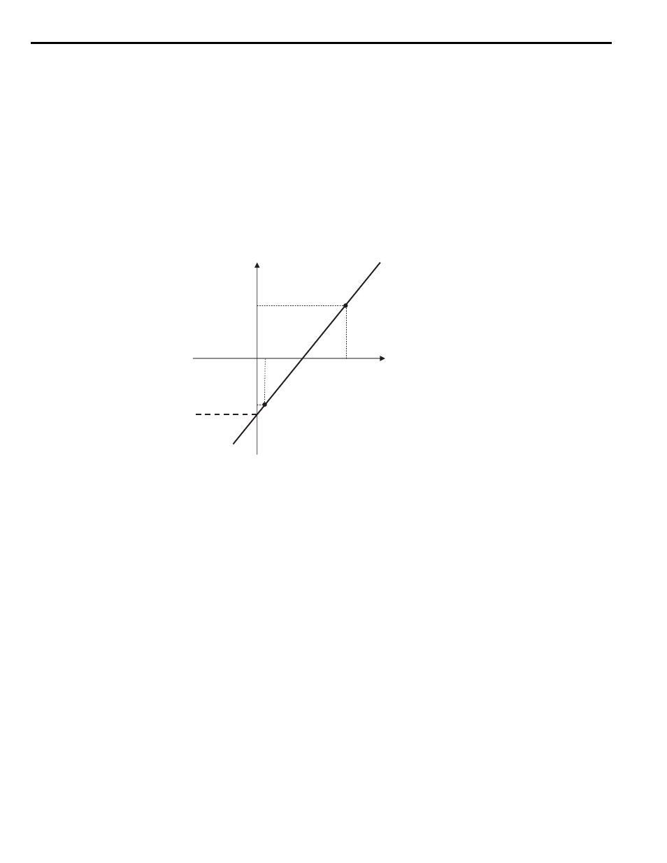
shows the Torque Compensation at Start settings with parameters S3-27 to S3-30.
indicates the torque compensation at start when the elevator moves up or down.
Figure 4.16
Figure 4.21 Torque Compensation at start for the Elevator in Up and Down Direction
After setting load conditions 1 and 2, perform a trial run. If required, parameter S3-12 can be set up to add a bias to the
load sensor input when riding in a Down direction (default: 0.0%, same torque compensation characteristics in up and
down direction).
illustrates the effect of torque compensation on the settings of S3-12 and S3-27 through S3-
30.
Analog Input Voltage (V)
S3-30
(Analog input
from Load Sensor
with Load Condition 2)
S3-29
(Analog Input from
Load Sensor
with Load
Condition 1)
S3-27
(Torque Compensation Value
with Load Condition 1)
S3-28
(Torque Compensation
Value with Load Condition 2)
0
During Load Condition 2
During Load Condition 1
Torque Compensation Value