A1-02 (control mode) dependent parameters, Motor 2 control parameters – Yaskawa L1000E AC Drive Technical Manual for CIMR-LE Models for Elevator Applications User Manual
Page 412
412
YASKAWA ELECTRIC SIEP YAIL1E 01A YASKAWA AC Drive L1000E Technical Manual
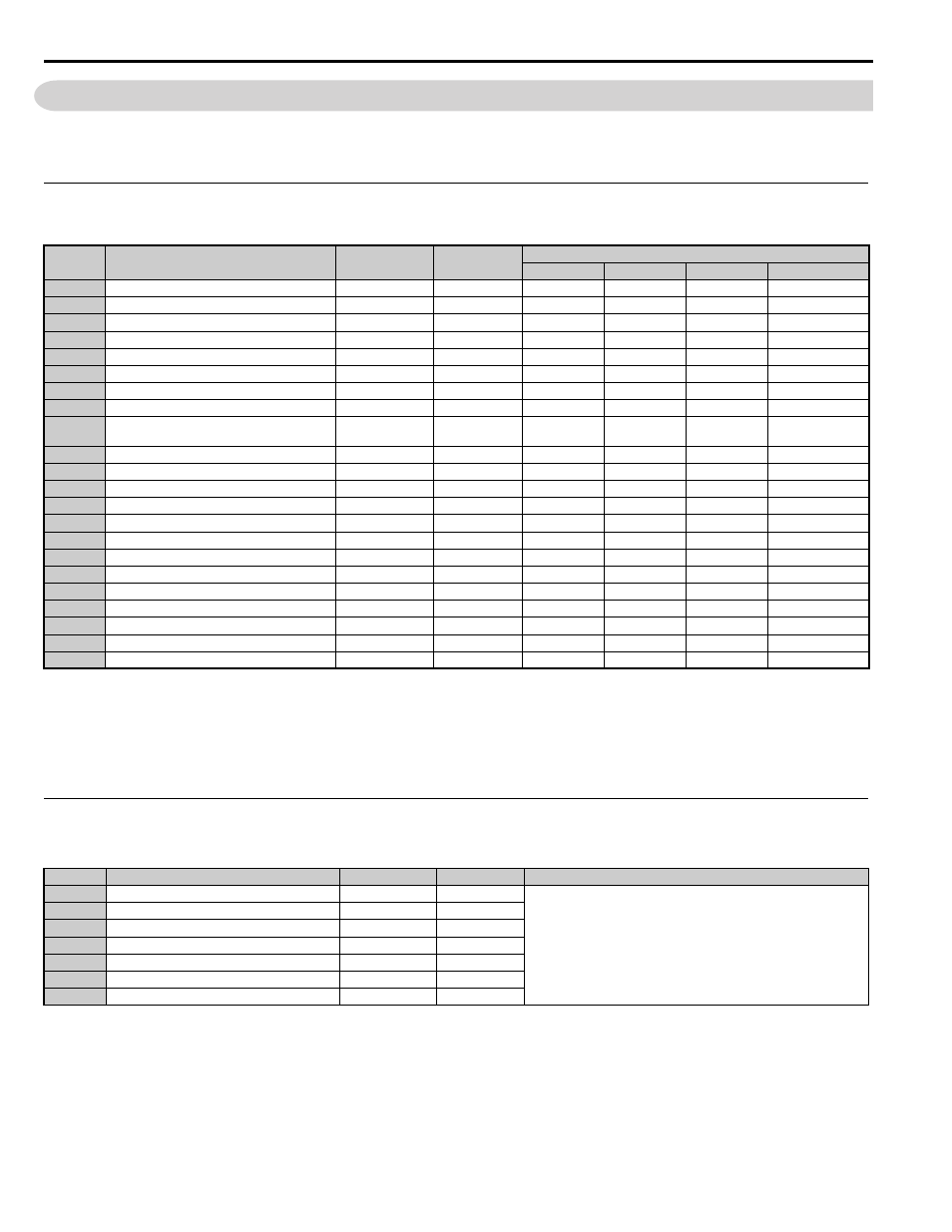
B.4 Control Mode Dependent Parameter Default Values
B.4 Control Mode Dependent Parameter Default Values
The tables below list parameters that depend on the control mode selection (A1-02 for motor 1, E3-01 for motor 2).
Changing the control mode initializes these parameters to the values shown here.
◆ A1-02 (Control Mode) Dependent Parameters
Table B.2 A1-02 (Control Mode) Dependent Parameters and Default Values
◆ Motor 2 Control Parameters
Table B.3 Motor 2 Control Parameters and Default Values
No.
Name
Setting Range
Resolution
Control Modes (A1-02)
V/f (0)
OLV (2)
CLV (3)
CLV/PM (7)
C3-05
<3> For models 2A0018 to 2A0225 and 4A0009 to 4A0114, the default setting is 16.1 for E1-08, and 8.0 for E1-10. For models 2A0269 to 2A0432
and 4A0140 to 4A0260, the default setting is 13.8 for E1-08 and, 6.9 for E1-10.
<9> Values shown here are for 200 V class drives. Double the value when using a 400 V class drive.
<22> Default setting value varies by drive model (o2-04).The default setting for models 2A0144 to 2A0432 and 4A0140 to 4A0260 is 1000 ms
when using V/f control.
<23> Setting range depends on the type of motor being used. An induction motor has a setting range of 10.0 to 120.0 Hz, while a PM motor has a
setting range of 4.0 to 120.0 Hz.
Output Voltage Limit Operation Selection
0, 1
–
–
1
1
0
C4-02
Torque Compensation Primary Delay Time
0 to 60000
1 ms
200
50
–
–
C5-01
Speed Control Loop Proportional Gain 1
0.00 to 300.00
0.01
–
–
40.00
3.00
C5-02
Speed Control Loop Integral Time 1
0.000 to 10.000
0.001 s
–
–
0.500
0.300
C5-03
Speed Control Loop Proportional Gain 2
0.00 to 300.00
0.01
–
–
20.00
3.00
C5-07
Speed Control Loop Gain Switching Speed
0.0 to 100.0
0.1%
–
–
0.0
2.0
C5-13
Speed Control Loop Proportional Gain 3
0.00 to 300.00
0.01
–
–
40.00
3.00
C5-14
Speed Control Loop Integral Time 3
0.000 to 10.000
0.001 s
–
–
0.500
0.300
C5-19
Speed Control Loop Proportional Gain Time
during Position Lock
0.00 to 300.00
0.01
–
–
40.00
10.00
E1-04
Maximum Output Frequency
0.1 Hz/1 rpm
50.0 Hz
50.0 Hz
50.0 Hz
150 rpm
E1-06
Base Frequency
0.0 to 120.0
0.1 Hz/1 rpm
50.0 Hz
50.0 Hz
50.0 Hz
150 rpm
E1-07
Middle Output Frequency
0.0 to 120.0
0.1 Hz
2.5
3.0
–
–
E1-08
Middle Output Frequency Voltage
0.0 to 255.0
0.1 V
12.6 Hz
–
–
E1-09
Minimum Output Frequency
0.0 to 120.0
0.1 Hz/1 rpm
0.5 Hz
0.5 Hz
0.0 Hz
0 rpm
E1-10
Minimum Output Frequency Voltage
0.0 to 255.0
0.1 V
2.3 Hz
–
–
F1-01
Encoder 1 Resolution
1 to 60000
1 ppr
–
1024
2048
F1-05
Encoder 1 Rotation Direction Selection
0, 1
–
–
–
0
1
L1-01
Motor Overload Protection Selection
0 to 3, 5
–
1
1
1
5
o1-04
V/f Pattern Setting Units
0, 1
–
–
–
0
1
o1-22
Mechanical Gear Ratio
0.10 to 50.00
0.01
–
–
14.00
1.00
S1-01
Zero Speed Level at Stop
0.0000 to 9.999
0.001%
2.400
1.000
0.200
0.350
S4-04
Light Load Direction Search Speed Reference
0.00 to 20.00
0.01%
5.00
5.00
5.00
10.00
No.
<18> Values shown here are for 200 V class drives. Double the value when using a 400 V class drive.
Name
Setting Range
Resolution
Control Mode: V/f
E3-04
Motor 2 Maximum Output Frequency
40.0 to 400.0
0.1 Hz
The default settings of these parameters depend on drive capacity.
E3: V/f Pattern for Motor 2 on page 182
E3-05
Motor 2 Maximum Output Voltage
0.0 to 255.0
0.1 V
E3-06
Motor 2 Base Frequency
0.0 to 400.0
0.1 Hz
E3-07
Motor 2 Mid Output Frequency
0.0 to 400.0
0.1 Hz
E3-08
Motor 2 Mid Output Frequency Voltage
0.0 to 255.0
0.1 V
E3-09
Motor 2 Minimum Output Frequency
0.0 to 400.0
0.1 Hz
E3-10
Motor 2 Minimum Output Voltage
0.0 to 255.0
0.1 V