5 e: motor parameters, E1: v/f pattern, E1-01: input voltage setting – Yaskawa L1000E AC Drive Technical Manual for CIMR-LE Models for Elevator Applications User Manual
Page 178: E1-03: v/f pattern selection, Figure 5.13 illustrates the v/f pattern setting, E1-01 related values
178
YASKAWA ELECTRIC SIEP YAIL1E 01A YASKAWA AC Drive L1000E Technical Manual
5.5 E: Motor Parameters
5.5 E: Motor Parameters
E parameters cover V/f pattern and motor data settings.
◆ E1: V/f Pattern
■
E1-01: Input Voltage Setting
Adjusts the levels of some protective features of the drive (overvoltage, Stall Prevention, etc.). Set this parameter to the
nominal voltage of the AC power supply.
NOTICE: Set parameter E1-01 to match the input voltage of the drive. The drive input voltage (not motor voltage) must be set in E1-01
for the protective features to function properly. Failure to set the correct drive input voltage will result in improper drive operation.
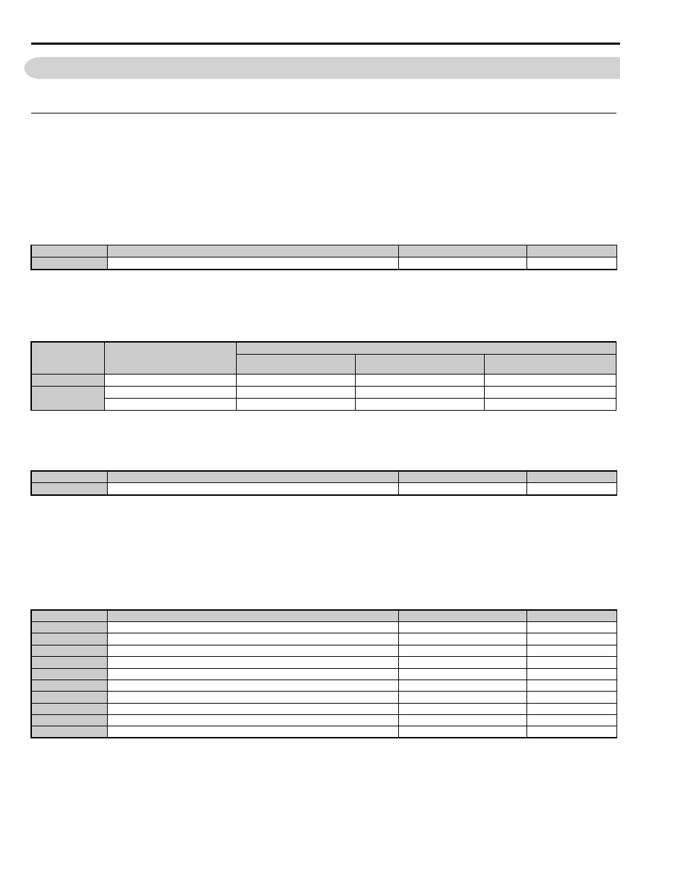
E1-01 Related Values
For 400 V class drives, the input voltage setting determines the undervoltage detection levels.
■
E1-03: V/f Pattern Selection
Note: Parameter is not reset to the default value when the drive is initialized using A1-03.
■
V/f Pattern Settings E1-04 to E1-13
illustrates the V/f pattern setting.
NOTICE: The motor may require more acceleration torque with drive operation than with a commercial power supply. Set a proper V/f
pattern by checking the load torque characteristics of the elevator to be used with the motor.
No.
<1> Values shown here are specific to 200 V class drives; double the values for 400 V class drives.
Parameter Name
Setting Range
Default
Input Voltage Setting
155 to 255 V
230 V
Voltage
Setting Value of
E1-01
(Approximate Values)
ov Detection Level
Braking Transistor
Operation Level
<1> The braking transistor operation levels are valid for the internal braking transistor of the drive. When using an external CDBR braking chopper,
refer to the instruction manual of that unit.
Uv Detection Level
(L2-05)
200 V Class
All settings
410 V
394 V
190 V
400 V Class
setting
≥ 400 V
820 V
788 V
380 V
setting < 400 V
820 V
788 V
350 V
No.
Parameter Name
Setting Range
Default
E1-03
V/f Pattern Selection
F
F
No.
<1> Setting range depends on the control mode being used. CLV allows a setting range of 10.0 to 120.0 Hz, while CLV/PM allows a setting range
of 4.0 to 120.0 Hz.
<2> Default setting is determined by the control mode (A1-02).
<3> Values shown here are for 200 V class drives. Double values when using a 400 V class unit.
<4> Default setting is determined by the drive model (o2-04).
<5> Parameter ignored when E1-11 and E1-12 are set to 0.0.
<6> Auto-Tuning will set E1-13 to the same value as E1-05.
Parameter Name
Setting Range
Default
E1-04
Maximum Output Frequency
10.0 to 120.0 Hz
E1-05
Maximum Voltage
0.0 to 255.0 V
230.0 V
E1-06
Base Frequency
0.0 to 120.0 Hz
E1-07
Middle Output Frequency
0.0 to 120.0 Hz
3.0 Hz
E1-08
Middle Output Frequency Voltage
0.0 to 255.0 V
E1-09
Minimum Output Frequency
0.0 to 120.0 Hz
E1-10
Minimum Output Frequency Voltage
0.0 to 255.0 V
E1-11
Middle Output Frequency 2
0.0 to 120.0 Hz
0.0 Hz
Middle Output Frequency Voltage 2
0.0 to 255.0 V
E1-13
Base Voltage
0.0 to 255.0 V
0.0 V