B.2 parameter groups – Yaskawa L1000E AC Drive Technical Manual for CIMR-LE Models for Elevator Applications User Manual
Page 367
B.2 Parameter Groups
YASKAWA ELECTRIC SIEP YAIL1E 01A YASKAWA AC Drive L1000E Technical Manual
367
Pa
ra
met
er
L
is
t
B
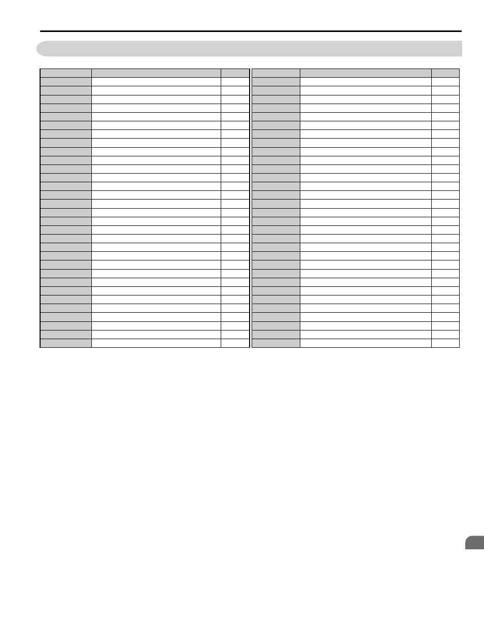
B.2 Parameter Groups
Parameter Group
Name
Page
Parameter Group
Name
Page
A1
Initialization
L1
Motor Protection
A2
User Parameters
L2
Undervoltage Detection
b1
Operation Mode Selection
L3
Stall Prevention
b2
Magnetic Flux Compensation
L4
Speed Detection
b4
Delay Timers
L5
Fault Reset
b6
Dwell Function
L6
Torque Detection
b7
Droop Control
L7
Torque Limit
b8
Energy Saving
L8
Drive Protection
C1
Acceleration and Deceleration Ramps
n1
Hunting Prevention
C2
Jerk Settings
n2
Speed Feedback Detection Control (AFR) Tuning
C3
Slip Compensation
n5
Inertia Compensation
C4
Torque Compensation
n6
Online Tuning
C5
Speed Control Loop Settings
n8
PM Motor Control Tuning
C6
Carrier Frequency
n9
Current Detection Adjustments
d1
Speed Reference
o1
Digital Operator Display Selection
d6
Field Forcing
o2
Digital Operator Keypad Functions
E1
V/f Pattern
o3
Copy Function
E2
Motor Parameters
o4
Maintenance Monitor Settings
E3
V/f Pattern for Motor 2
S1
Brake Sequence
E4
Motor 2 Parameters
S2
Slip Compensation for Elevators
E5
PM Motor Settings
S3
Start/Stop Optimization
F1
Encoder/PG Feedback Settings
S4
Rescue Operation
F3
Digital Input Card (DI-A3)
S5
Short Floor Operation
F4
Analog Monitor Card (AO-A3)
S6
Error Detection
F5
Digital Output Card (DO-A3)
T1
Induction Motor Auto-Tuning
F6
Communication Option Card
T2
PM Motor Auto-Tuning
H1
Multi-Function Digital Inputs
U1
Operation Status Monitors
H2
Multi-Function Digital Outputs
U2
Fault Trace
H3
Multi-Function Analog Inputs
U3
Fault History
H4
Multi-Function Analog Outputs
U4
Maintenance Monitors
H5
MEMOBUS/Modbus Serial Communication
U6
Control Monitors