N5-03: inertia compensation gain, Speed feedback compensation: speed observer, 9 n: special adjustments – Yaskawa L1000E AC Drive Technical Manual for CIMR-LE Models for Elevator Applications User Manual
Page 234
5.9 n: Special Adjustments
234
YASKAWA ELECTRIC SIEP YAIL1E 01A YASKAWA AC Drive L1000E Technical Manual
Measuring Acceleration Time
Take the following steps when measuring the motor acceleration time.
1.
Decouple motor and load.
2.
Perform Auto-Tuning or manually enter the correct motor data.
3.
Properly set up the speed loop (ASR).
4.
Set the acceleration time to zero.
5.
Set the forward torque limit in parameter L7-01 to 100%.
6.
Set the speed reference equal to the motor rated speed.
7.
While monitoring the motor speed in U1-05, start the motor in the forward direction and measure the time it takes
to reach the rated speed.
8.
Reverse the parameter settings above and set the measured time to parameter n5-02.
■
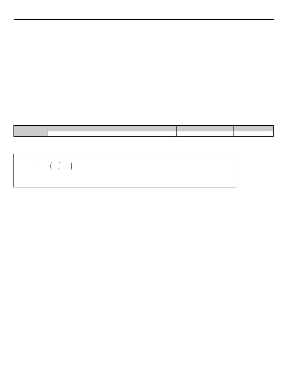
n5-03: Inertia Compensation Gain
Parameter n5-03 sets the inertia ratio of the load connected to the motor.
Calculate the value for n5-03 as explained below.
■
Speed Feedback Compensation: Speed Observer
Enabling the Speed Feedback Compensation can reduce oscillation and increase responsiveness to the speed reference by
compensating for phase delay.
Note: 1. Set n5-07 to 1 to use the Speed Feedback Compensation.
2. Set C5-17 (motor inertia) and C5-18 (load inertia ratio) to the correct values before using the Speed Feedback Compensation.
3. If the product of C5-17
× C5-18 is relatively large, the estimated speed will be very slow.
4. Reduce the products of C5-17
× C5-18 if oscillation is a problem.
5. C5-18 to at least 1.1 when using the Speed Feedback Compensation. A setting of 1.0 or less disables the Speed Feedback
Compensation.
Adjusting the Speed Feedback Compensation
Follow the procedure below to set up the Speed Feedback Compensation
1.
Set the drive for Closed Loop Vector for PM motors.
2.
Enter the correct data from the motor nameplate and the motor test report to the E5- parameters.
3.
Set all ASR-related parameters (C5-) to their most appropriate values.
4.
Set the Speed Feedback Compensation to operate in test mode (n5-07).
5.
Connect the ropes to the motor.
6.
Start operating the elevator while looking at the Speed Feedback Compensation output monitor (U6-56) and the
motor speed feedback (U1-05).
7.
Adjust the Speed Feedback Compensation gain (n5-08) and C5-18 so that the monitor values in U6-56 and U1-
05 are relatively low.
No.
Parameter Name
Setting Range
Default
n5-03
Inertia Compensation Gain
0.00 or 100.00
1.00
• J
Mot
- Motor inertia in kgm
2
• n
r_Mot
- Rated motor speed in r/min
• T
r_Mot
- Rated motor torque in Nm
• J
TS
- Traction sheave inertia in kgm
2
• i - Gear ratio (n
Load
/n
Mot
)
• v
r_Elev
- Rated elevator speed in m/s
•
Σm - Mass of all moved parts (car, counterweight, ropes, load
) in kg
<1> Insert 0 kg for the load to calculate the lowest setting, insert the elevator rated load to calculate the maximum setting for
n5-03. Use the lower of calculated values for initial trials and increase n5-03 gradually until the desired performance is
achieved.
ΣJ
= J
TS
i
2
+
Σm
30 v
r_Elev
π n
r_Mot
2
n5-03
=
ΣJ / J
Mot