Figure 5.34, 8 l: protection functions – Yaskawa L1000E AC Drive Technical Manual for CIMR-LE Models for Elevator Applications User Manual
Page 216
5.8 L: Protection Functions
216
YASKAWA ELECTRIC SIEP YAIL1E 01A YASKAWA AC Drive L1000E Technical Manual
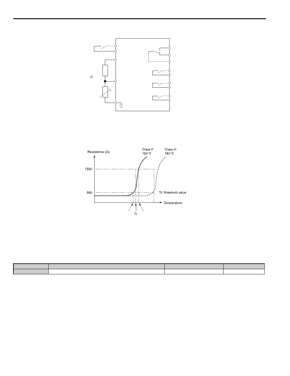
Figure 5.34
Figure 5.34 Connection of a Motor PTC Thermistor
The PTC thermistor must have the characteristics shown in
for one motor phase. The drives motor overload
detection requires three PTC thermistors to be connected in series.
Figure 5.35
Figure 5.35 Motor PTC Thermistor Characteristics
Overheat detection using a PTC thermistor is configured with parameters L1-03, L1-04, and L1-05 as explained below.
■
L1-03: Motor Overheat Alarm Operation Selection (PTC thermistor input)
Sets the drive operation when the PTC thermistor input signal reaches the motor overheat alarm level (oH3).
Setting 0: Ramp to stop
The drive stops the motor using the deceleration time 1 set in parameter C1-02.
Setting 1: Coast to stop
The drive output is switched off and the motor coasts to stop.
Setting 2: Emergency stop (Fast stop)
The drive stops the motor using the deceleration time set in parameter C1-09.
Setting 3: Alarm only
The operation is continued and an oH3 alarm is displayed on the digital operator.
No.
Parameter Name
Setting Range
Default
L1-03
Motor Overheat Alarm Operation Selection (PTC thermistor input)
0 to 3
3
Drive
+V
(+10.5 V, 20 mA)
Branch
resistor
12 k
PTC
thermistor
A2 (0-10 V)
AC
Multi-function digital input
MA
Fault output
Multi-function
digital outputs
MB
MC
M1
M2
M3
M4
M5
M6
Tr’
Tr + 5K (oH4 Fault Level)
Tr - 5K (oH3 Alarm Level)