2 b: application, B1: operation mode selection, B1-01: speed reference selection – Yaskawa L1000E AC Drive Technical Manual for CIMR-LE Models for Elevator Applications User Manual
Page 156

156
YASKAWA ELECTRIC SIEP YAIL1E 01A YASKAWA AC Drive L1000E Technical Manual
5.2 b: Application
5.2 b: Application
◆ b1: Operation Mode Selection
■
b1-01: Speed Reference Selection
Selects the frequency reference source for the REMOTE mode.
NOTICE: Always turn off the RUN command before changing the setting of parameters d1-18 (Speed Reference Selection Mode), b1-
01 (Speed Reference Selection), or H1-
(Multi-Function Digital Inputs). If the RUN command is on when changing any of these
settings, the motor may unexpectedly start running, and could result in injury.
Note: 1. If an Up/Down command is input to the drive but the speed reference entered is 0 or below the minimum frequency, the RUN
indicator LED on the digital operator will light.
2. Press the LO/RE key to set the drive to LOCAL and use the digital operator keypad to enter the speed reference.
Setting 0: Operator keypad
When b1-01 = 0, the user can enter the speed reference in the following ways:
• Switch between the speed references set to the d1- parameters according to the speed reference priority (d1-18) and
multi-function digital input terminal settings.
Refer to d1: Speed Reference on page 174
• Enter the speed reference directly using the digital operator keypad.
Instructions on changing speed reference settings can be found in
The Drive and Programming Modes on page 95
.
Setting 1: Terminals (analog input terminals)
If source of the speed reference is assigned to the control terminals (b1-01 = 1), then d1-18 will automatically be set to 0
so the drive uses multi-speed references d1-01 to d1-08. With this setting, the analog input terminal can be used to set the
speed reference. The drive will look to analog input terminals A1 or A2 for the speed reference (provided parameter H3-
02 or H3-10 must be set to “0”, assigning terminal A1 or A2 respectively to the speed reference). Parameter d1-18 is to be
set to 0.
Refer to d1: Speed Reference on page 174
Terminals A1 and A2 can accept a voltage signal to supply the speed reference to the drive.
shows the
parameter settings and voltage levels required for each terminal.
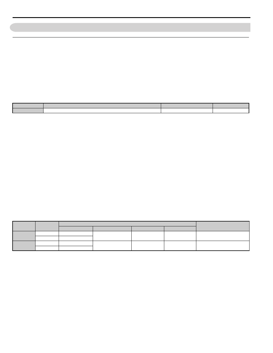
Table 5.5 Analog Input Settings for Speed Reference Using Voltage Signals
Setting 2: MEMOBUS/Modbus Communications
When b1-01 = 2, the speed reference is given to the drive using MEMOBUS/Modbus register 0002H. Setting the speed
reference from MEMOBUS/Modbus requires setting parameter d1-18 to 0.
Note: Be sure to program the digital inputs for speed selection and set parameter b1-02 to 0 when switching the preset speeds set in the
d1- parameters via MEMOBUS/Modbus. Select the desired speed by switching these digital inputs using the MEMOBUS/
Modbus operation command (0001H).
No.
Parameter Name
Setting Range
Default
b1-01
Speed Reference Selection
0 to 3
0
Terminal
Signal Level
Parameter Settings
Notes
Signal Level Selection
Function Selection
Gain
Bias
A1
0 to 10 Vdc
H3-01 = 0
H3-02 = 0
(speed reference bias)
H3-03
H3-04
–
-10 to +10 Vdc
H3-01 = 1
A2
0 to 10 Vdc
H3-09 = 0
H3-10 = 0
(speed reference bias)
H3-11
H3-12
–
-10 to +10 Vdc
H3-09 = 1