Adjustments for elevator ride comfort, Figure 4.24, Show timing charts for elevator – Yaskawa L1000E AC Drive Technical Manual for CIMR-LE Models for Elevator Applications User Manual
Page 130: Speed loop adjustments (clv and clv/pm), Inertia compensation (clv and clv/pm), 6 setup procedure for elevator applications
4.6 Setup Procedure for Elevator Applications
130
YASKAWA ELECTRIC SIEP YAIL1E 01A YASKAWA AC Drive L1000E Technical Manual
Figure 4.19
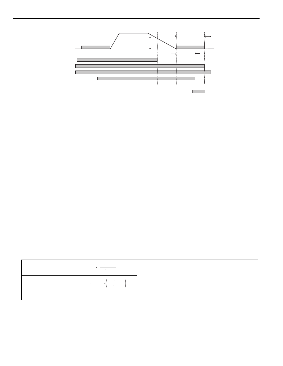
Figure 4.24 With Up/Down Command Cleared and U1-05 < S1-26
◆ Adjustments for Elevator Ride Comfort
This section explains the adjustment of drive settings used to eliminate problems with hunting, vibration, and rollback.
Perform the steps presented in this section after the Basic Application Setup procedure is complete. Also refer to
Comfort Related Problems on page 145
for further descriptions on how to resolve riding comfort problems.
■
Speed Loop Adjustments (CLV and CLV/PM)
The speed control loop uses four different gain and integral time settings that can be adjusted using C5- parameters.
The settings are switched over when the motor speed reaches the level set in parameter C5-07.
• Proportional gain and integral time C5-03/04 are used at start when the speed is lower than the setting of C5-07.
• Proportional gain and integral time C5-01/02 are used at speeds above the setting of C5-07.
• Proportional gain and integral time C5-13/14 are used at stop when leveling speed is selected as speed reference and the
speed is lower than the setting of C5-07.
• Proportional gain and integral time C5-19/20 are used During Position Lock at start in CLV/PM.
Increase the gain and shorten the integral time to increase speed control responsiveness in each of the sections. Reduce
the gain and increase the integral time if vibration or oscillation occurs.
■
Inertia Compensation (CLV and CLV/PM)
Inertia compensation can be used to eliminate motor speed overshoot at the end of acceleration or undershoot at the end of
deceleration caused by the system inertia. Adjust the function following the steps below.
1.
Properly adjust the speed control loop parameters (C5-).
2.
Set parameter n5-01 to 1 to enable inertia compensation.
3.
Calculate and set n5-02 and n5-03 as follows:
4.
Change the setting of n5-03 within the limits calculated in step 3 until the desired performance is achieved.
If possible, trace the output speed after soft starter (U1-16) and the motor speed (U1-05) values. Increase n5-03
if the motor speed does not follow the speed after soft start. Decrease n5-03 if the motor overshoots the
designated speed at the end of acceleration or undershoots the speed at the end of deceleration.
Motor Acceleration Time n5-02
<1> Insert 0 kg for the load to calculate the lowest setting, insert the elevator rated load to calculate the maximum setting for n5-03. Use the
lower setting for initial trials.
• J
Mot
- Motor inertia in kgm
2
• n
r_Mot
- Rated motor speed in min
-1
• T
r_Mot
- Rated motor torque in Nm
• J
TS
- Traction sheave inertia in kgm
2
• i - Gear ratio (n
Load
/n
Mot
)
• v
r_Elev
- Rated elevator speed in m/s
•
Σm - Mass of all moved parts (car, counterweight, ropes, load
Inertia Compensation Gain
n5-03
Speed
Enabled
DC Injection Braking/
Position Lock at Start
Selected Speed
S1-26
Emergency Stop
Start Level
S1-11
(Output Contactor Open
Delay Time)
S1-07
(Brake Close
Delay Time)
S1-05
(DC Injection/Position
Lock Time at stop)
DC Injection/
Position Lock at Stop
Up/Down Command
Safe disable (terminals H1/H2 on)
or Baseblock off (H1-
= 8/9)
H2-
= 51 (Output Cont. Contr.)
H2-
= 50 (Brake Control)
n5-02
= J
Mot
π n
r_Mot
30 T
r_Mot
ΣJ
= J
TS
i
2
+
Σm
30 v
r_Elev
π n
r_Mot
2
n5-03
=
ΣJ / J
Mot