Yea_comm – Yaskawa L1000E AC Drive Technical Manual for CIMR-LE Models for Elevator Applications User Manual
Page 344
8.4 Option Card Installation
344
YASKAWA ELECTRIC SIEP YAIL1E 01A YASKAWA AC Drive L1000E Technical Manual
7.
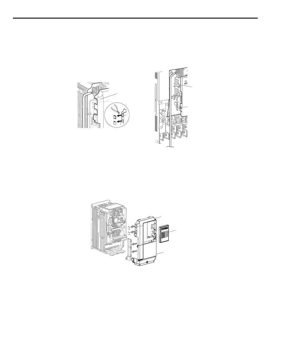
Route the option wiring.
Depending on the drive model, some drives may require routing the wiring through the side of the front cover to
the outside. For drive models 2A0018 through 2A0041 and 4A0009 through 4A0023, cut out the perforated
openings on the left side of the drive front cover as shown in
-A and leave no sharp edges to damage
wiring.
Route the wiring inside the enclosure as shown in
-B for drive models 2A0059 through 2A0432 and
4A0030 through 4A0260 that do not require routing through the front cover.
Figure 8.9
Figure 8.11 Wire Routing Examples
8.
Replace and secure the front covers of the drive (D, F) and replace the digital operator (E).
Figure 8.10
Figure 8.12 Replace the Front Covers and Digital Operator
Note: Take proper precautions when wiring the option so that the front covers will easily fit back onto the drive. Make sure cables are
not pinched between the front covers and the drive when replacing the covers.
A – Route wires through the openings
provided on the left side of the
front cover.
(2A0018 to 2A0041 and
4A0009 to 4A0023)
<1> The drive will not meet NEMA Type 1 requirements if wiring is exposed outside the enclosure.
B – Use the open space provided
inside the drive to route option
wiring.
(2A0059 to 2A0432 and
4A0030 to 4A0260)
B
A
D
E
F
PWR
LED MO
NITOR
JVOP
-184
RUN
DS1
DS2
RUN
DS1
DS2
STATU
S
READY
RUN
ALARM
(RUN)
PGOH,
LT
BB,HB
B
EF,SE
Other
Fault
OV,UV
OH,OL
OC,GF,
SC,PGO
CPF,O
FA,OFB,O
FC
:LIGH
T
:BLIN
K
:LIGH
T OFF
YEA_comm