Ection, L1-02: motor overload protection time, Common_tmo – Yaskawa L1000E AC Drive Technical Manual for CIMR-LE Models for Elevator Applications User Manual
Page 215: 8 l: protection functions
5.8 L: Protection Functions
YASKAWA ELECTRIC SIEP YAIL1E 01A YASKAWA AC Drive L1000E Technical Manual
215
P
a
ra
me
te
r De
ta
ils
5
■
L1-02: Motor Overload Protection Time
This setting rarely requires adjustment. Sets the time it takes the drive to detect motor overheat due to overload. If the
motor overload tolerance protection time when an overload of 150% is imposed after continuous operation at 100% is
clear, set that time as the value.
Defaulted to operate with an allowance of 150% overload operation for one minute in a hot start; after continuous
operation at 100%.
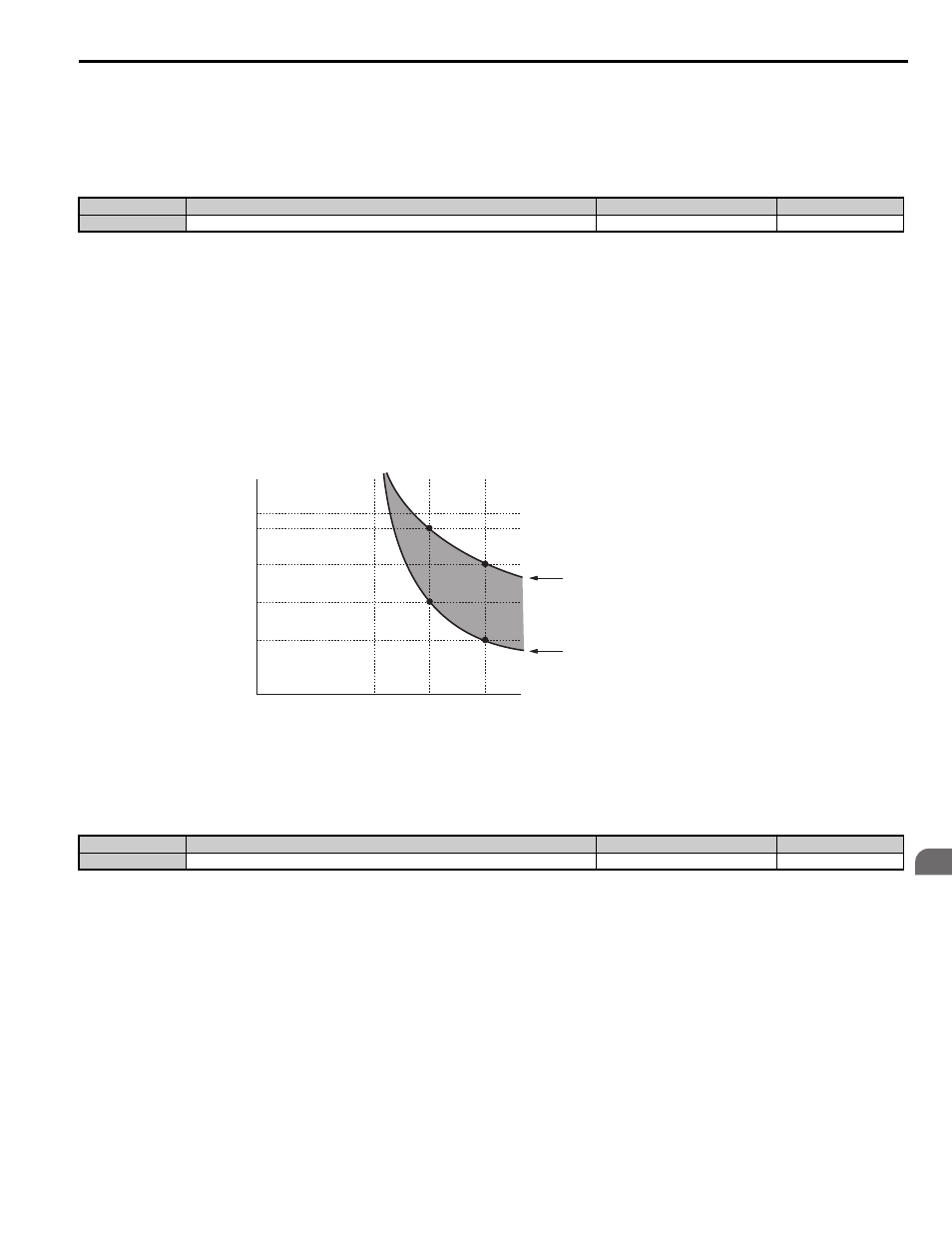
shows an example of the electrothermal protection operation time using a general-purpose motor operating at
the value of E1-06, Motor Base Speed, with L1-02 set to one minute.
Motor overload protection operates in the area between a cold start and a hot start.
• Cold start: Characteristics of motor protection operation time in response to an overload situation that was suddenly
reached when starting a stationary motor.
• Hot start: Characteristics of motor protection operation time in response to an overload situation that occurred while the
motor was operating continuously at or below its rated current.
Figure 5.33
Figure 5.33 Protection Operation Time for General Purpose Motors at the Rated Output Frequency
■
L1-13: Continuous Electrothermal Operation Selection
Determines whether to hold the current value of the electrothermal motor protection (L1-01) when the power supply is
interrupted.
Setting 0: Disabled
Setting 1: Enabled
■
Motor Protection Using a Positive Temperature Coefficient (PTC thermistor)
A motor PTC thermistor can be connected to an analog input of the drive. This input is used by the drive for motor
overheat protection.
When the PTC thermistor input signal reaches the motor overheat alarm level, an oH3 alarm will be triggered and the
drive will continue operation according to the setting of L1-03. When the PTC thermistor input signal reaches the
overheat fault level, an oH4 fault will be triggered, a fault signal will be output, and the drive will stop the motor using the
stop method setting in L1-04.
Connect the PTC thermistor between terminals AC and A2 as shown in
. Set parameter H3-09 to 0 and
parameter H3-10 to E
No.
Parameter Name
Setting Range
Default
L1-02
Motor Overload Protection Time
0.1 to 5.0 min
1.0 min
No.
Parameter Name
Setting Range
Default
L1-13
Continuous Electrothermal Operation Selection
0 or 1
1
common_TMo
Operation time (minutes)
Cold start
(Characteristics when an overload occurs
at a complete stop)
Hot start
(Characteristics when an overload occurs
during continuous operation at 100%)
Motor current (%)
E2-01 = 100% motor current
10
7
3
1
0.4
0.1
0
100
150
200