A.3 drive specifications – Yaskawa L1000E AC Drive Technical Manual for CIMR-LE Models for Elevator Applications User Manual
Page 360
360
YASKAWA ELECTRIC SIEP YAIL1E 01A YASKAWA AC Drive L1000E Technical Manual
A.3 Drive Specifications
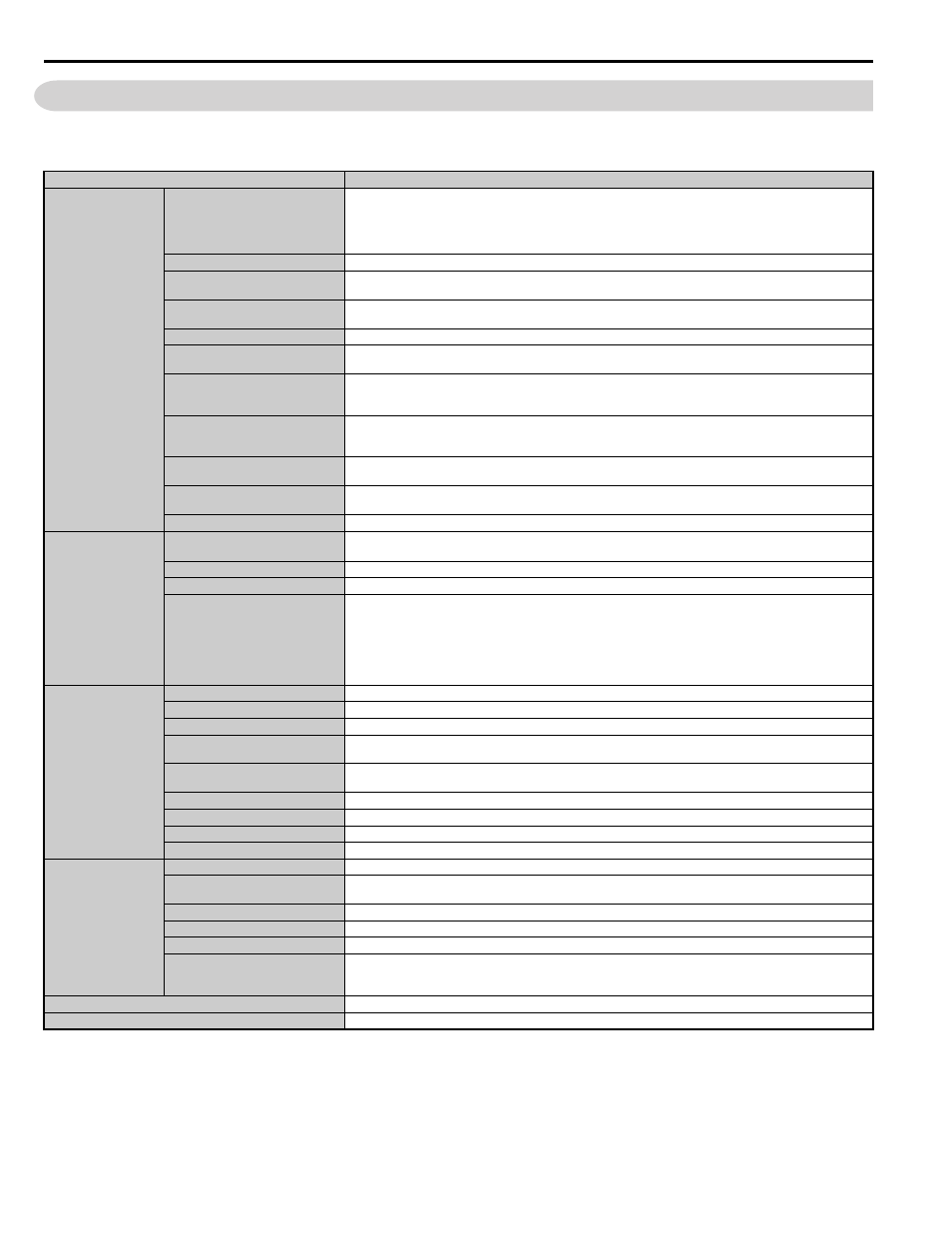
A.3 Drive Specifications
Note: 1. Perform rotational Auto-Tuning to obtain the performance specifications given below.
2. For optimum performance life of the drive, install the drive in an environment that meets the required specifications.
Item
<1> The accuracy of these values depends on motor characteristics, ambient conditions, and drive settings. Specifications may vary with different
motors and with changing motor temperature. Contact Yaskawa for consultation.
<2> Overload protection may be triggered when operating with 133% of the rated output current if the output speed is less than 6 Hz.
<3> Ground protection cannot be provided when the impedance of the ground fault path is too low, or when the drive is powered up while a ground
fault is present at the output.
Specification
Control Characteristics
Control Method
The following control methods can be set using drive parameters:
• V/f Control (V/f)
• Open Loop Vector Control (OLV)
• Closed Loop Vector Control (CLV)
• Closed Loop Vector Control for PM (CLV/PM)
Frequency Control Range
0.01 to 120 Hz
Frequency Accuracy
(Temperature Fluctuation)
Digital input: within ±0.01% of the max output speed (-10 to +40 °C)
Analog input: within ±0.1% of the max output speed (25 °C ±10 °C)
Frequency Setting Resolution
Digital inputs: 0.01 Hz
Analog inputs: 1/2048 of the maximum output speed setting (11 bit plus sign)
Output Speed Resolution
0.001 Hz
Frequency Setting Signal
Main speed frequency reference: DC -10 to +10 V (20 k
Ω), DC 0 to +10 V (20 kΩ), 4 to 20 mA (250 Ω), 0 to 20 mA
(250
Ω)
Starting Torque
V/f: 150% at 3 Hz
OLV: 200% at 0.3 Hz
CLV, CLV/PM: 200% at 0 r/min
Speed Control Range
V/f: 1:40
OLV: 1:200
CLV, CLV/PM: 1:1500
Speed Control Accuracy
OLV:
±0.2% (25°C ±10°C)
CLV:
±0.02% (25°C ±10°C)
Speed Response
OLV: 10 Hz (25°C ±10°C)
CLV: 50 Hz (25°C ±10°C)
Torque Limit
Parameters setting allow separate limits in four quadrants (available in OLV, CLV, CLV/PM)
Control Characteristics
Accel/Decel Ramp
0.0 to 6000.0 s (4 selectable combinations of independent acceleration and deceleration settings, unit changeable to m/s
2
or ft/s
2
)
Braking Transistor
Models CIMR-LE2A0018 to 2A0144, 4A0009 to 4A0075 have a built-in braking transistor.
V/f Characteristics
Freely programmable
Main Control Functions
Inertia Compensation, Position Lock at Start and Stop/Anti-Rollback Function, Overtorque/Undertorque Detection,
Torque Limit, Speed Reference, Accel/decel Switch, 5 Zone Jerk Settings, Auto-Tuning (Stationary and Rotational
Motor/Encoder Offset Tuning), Dwell, Cooling Fan on/off Switch, Slip Compensation, Torque Compensation, DC
Injection Braking at Start and Stop, MEMOBUS/Modbus Comm. (RS-422/485 max, 115.2 kbps), Fault Reset,
Removable Terminal Block with Parameter Backup Function, Online Tuning, High Frequency Injection, Short Floor,
Rescue Operation (Light Load Direction Search Function), Inspection Run, Brake Sequence, Speed related parameters
with elevator units display, etc.
Protection Functions
Motor Protection
Electronic thermal overload relay
Momentary Overcurrent Protection
Drive stops when output current exceeds 200% of rated output current
Overload Protection
Drive stops after 30 s at 133% of rated output current
Overvoltage Protection
200 V class: Stops when DC bus voltage exceeds approx. 410 V
400 V class: Stops when DC bus voltage exceeds approx. 820 V
Undervoltage Protection
200 V class: Stops when DC bus voltage falls below approx. 190 V
400 V class: Stops when DC bus voltage falls below approx. 380 V
Heatsink Overheat Protection
Thermistor
Stall Prevention
Stall Prevention is available during acceleration, and during run.
Ground Protection
Electronic circuit protection
DC Bus Charge LED
Remains lit until DC bus voltage falls below 50 V
Environment
Area of Use
Indoors
Ambient Temperature
IP00 enclosure with top protective cover: -10 to +40
°C
IP00 enclosure: -10 to +50
°C
Humidity
95 RH% or less (no condensation)
Storage Temperature
-20 to 60
°C (short-term temperature during transportation)
Altitude
Up to 1000 meters without derating, up to 3000 m with output current and voltage derating
Vibration/Shock
10 to 20 Hz: 9.8 m/s
2
20 to 55 Hz: 5.9 m/s
2
(2A0018 to 2A0225 and 4A0009 to 4A0188) or 2.0 m/s
2
(2A0269 to 2A0432 and 4A0225 to
4A0260)
Standards
• UL Underwriters Laboratories Inc: UL508C Power Conversion Equipment
Protection Design
IP00 enclosure with top protective cover, IP00