6 setup procedure for elevator applications, Following the wiring diagram show in figure 4.28, Starting rescue operation 1 – Yaskawa L1000E AC Drive Technical Manual for CIMR-LE Models for Elevator Applications User Manual
Page 136: Ending rescue operation 1
4.6 Setup Procedure for Elevator Applications
136
YASKAWA ELECTRIC SIEP YAIL1E 01A YASKAWA AC Drive L1000E Technical Manual
■
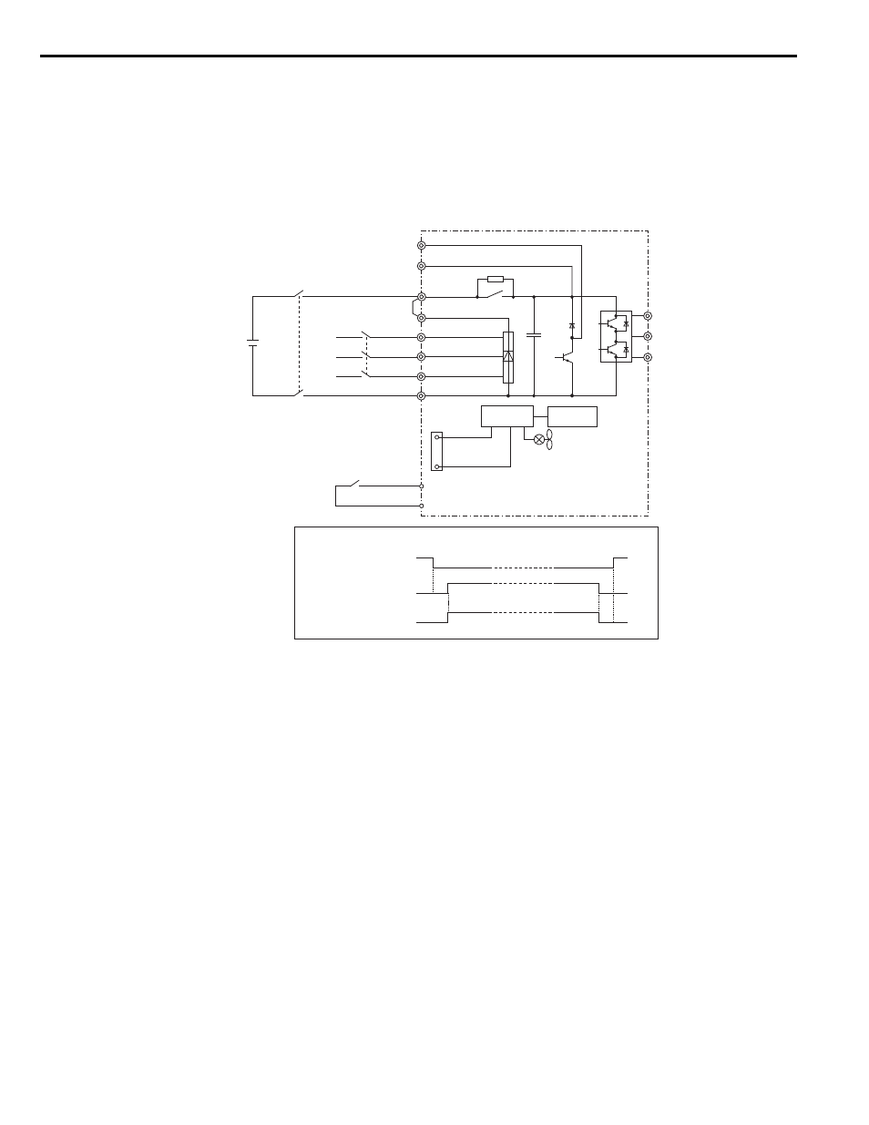
Using a Single Battery with Minimum 250 Vdc (500 Vdc)
Follow the instructions when using one battery to supply both, main circuit and controller. The battery voltage must be at
least 250 Vdc for 200 V class drives or 500 Vdc for 400 V class drives.
Wiring
Following the wiring diagram show in
.
Figure 4.23
Figure 4.28 Using a Backup Battery With Minimum 250 Vdc (500 Vdc)
Operation Sequence
Starting Rescue Operation
1.
Open contactor B.
2.
Set the input terminal programmed for Rescue Operation (H1- = 55).
3.
Close contactor A.
4.
Set the Up/Down command.
Ending Rescue Operation
1.
After the car has stopped, open contactor A.
2.
Clear the input terminal set for Rescue Operation (H1- = 55).
3.
Close contactor B to return to operation with normal power supply.
-
L1000E
DC bus power supply
L1
L2
L3
CN19
1
4
W/T3
V/T2
U/T1
R/L1
S/L2
T/L3
B1
B2
SC
H1-
ڧڧ = 55
(Rescue Operation)
Battery for DC bus
250 to 340 Vdc
500 to 680 Vdc
Magnetic Contactor A
Magnetic Contactor B
Control
circuit
Power supply
Magnetic Contactor Sequence
H1-
ڧڧ = 55
(Rescue Operation)
Magnetic Contactor B
Magnetic Contactor A
S
3
to S
8