6 auto-tuning fault detection, Auto-tuning codes, causes, and possible solutions, Auto-tuning fault detection – Yaskawa L1000E AC Drive Technical Manual for CIMR-LE Models for Elevator Applications User Manual
Page 297: Auto-tuning fault, 1 and 2), Refer to auto-tuning fault
6.6 Auto-Tuning Fault Detection
YASKAWA ELECTRIC SIEP YAIL1E 01A YASKAWA AC Drive L1000E Technical Manual
297
T
ro
ubles
hoo
ting
6
6.6 Auto-Tuning Fault Detection
When the Auto-Tuning faults shown below are detected, the fault is displayed on the digital operator and the motor coasts
to a stop. Auto-Tuning faults do not trigger a multi-function terminal set for fault or alarm output.
An End error indicates that although Auto-Tuning has successfully completed, there is some discrepancy in the
calculations.
If an End error occurs, check for the cause of the error using the table below, and perform Auto-Tuning again after
fixing the problem. Start the application if no problem can be diagnosed despite the existence of the End error.
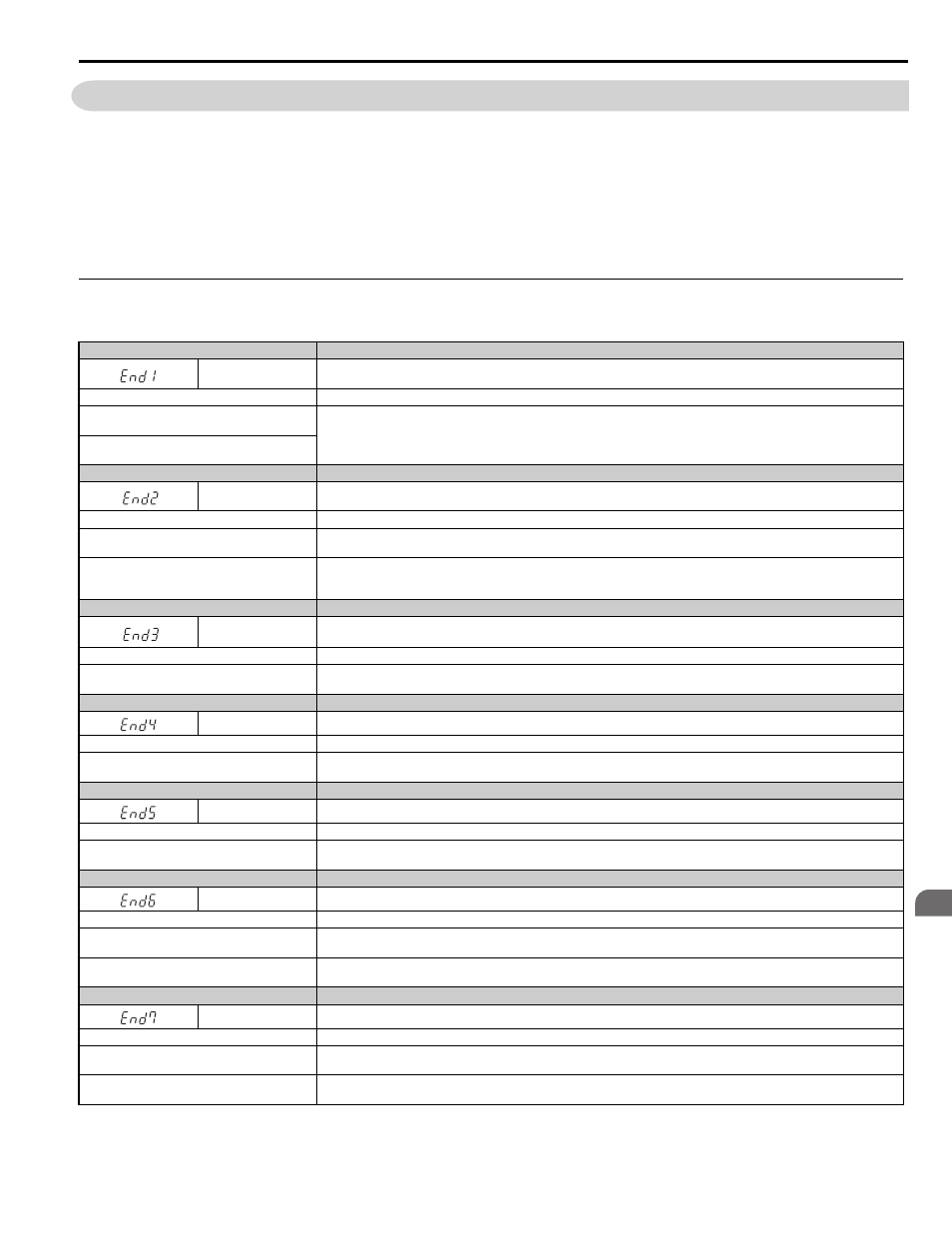
◆ Auto-Tuning Codes, Causes, and Possible Solutions
Table 6.11 Auto-Tuning Codes, Causes, and Possible Solutions
Digital Operator Display
Error Name
End1
Excessive V/f Setting (detected only during Rotational Auto-Tuning, and displayed after Auto-Tuning is complete)
Cause
Possible Solutions
The torque reference exceeded 20% during
Auto-Tuning.
• Before Auto-Tuning the drive, verify the information written on the motor nameplate and enter that data to T1-03 through T1-05.
• Enter proper information to parameters T1-03 to T1-05 and repeat Auto-Tuning.
The results from Auto-Tuning the no-load current
exceeded 80%.
Digital Operator Display
Error Name
End2
Motor Iron-Core Saturation Coefficient (detected only during Rotational Auto-Tuning and displayed after Auto-Tuning is complete)
Cause
Possible Solutions
Motor data entered during Auto-Tuning was
incorrect.
• Make sure the data entered to the T1 parameters match the information written on the motor nameplate.
• Restart Auto-Tuning and enter the correct information.
Results from Auto-Tuning are outside the parameter
setting range, assigning the iron-core saturation
coefficient (E2-07, E2-08) a temporary value.
Check and correct faulty motor wiring.
Digital Operator Display
Error Name
End3
Rated Current Setting Alarm (displayed after Auto-Tuning is complete)
Cause
Possible Solutions
The correct current rating printed on the nameplate
was not entered into T1-04.
• Check the setting of parameter T1-04.
• Check the motor data and repeat Auto-Tuning.
Digital Operator Display
Error Name
End4
Adjusted Slip Calculation Error
Cause
Possible Solutions
The slip that was calculated is outside the allowable
range.
• Make sure the data entered for Auto-Tuning is correct.
• Execute Rotational Auto-Tuning instead. If not possible, try Stationary Auto-Tuning 2.
Digital Operator Display
Error Name
End5
Resistance Tuning Error
Cause
Possible Solutions
The resistance value that was calculated is outside
the allowable range.
• Double-check the data that was entered for the Auto-Tuning process.
• Check the motor and motor cable connection for faults.
Digital Operator Display
Error Name
End6
Leakage Inductance Alarm
Cause
Possible Solutions
A1-02 setting error
• Check the setting of parameter A1-02.
• Check the control mode and repeat Auto-Tuning.
The leakage inductance value that was calculated is
outside the allowable range.
Double-check the data that was entered for the Auto-Tuning process.
Digital Operator Display
Error Name
End7
No-Load Current Alarm
Cause
Possible Solutions
The entered no-load current value was outside the
allowable range.
Check and correct faulty motor wiring.
Auto-Tuning results were less than 5% of the motor
rated current.
Double-check the data that was entered for the Auto-Tuning process.