Output terminals, Yea_common, 8 control circuit wiring – Yaskawa L1000E AC Drive Technical Manual for CIMR-LE Models for Elevator Applications User Manual
Page 74: Table 3.6 control circuit output terminals
3.8 Control Circuit Wiring
74
YASKAWA ELECTRIC SIEP YAIL1E 01A YASKAWA AC Drive L1000E Technical Manual
■
Output Terminals
lists the output terminals on the drive. Text in parenthesis indicates the default setting for each multi-function
output.
Note: Multi-function relay output terminals are rated at a minimum of 10 mA. If less than 10 mA is required, use the photocoupler
outputs (P1-C1, P2-C2). Using the wrong current output level may cause the output to malfunction when the terminal is activated.
Table 3.6 Control Circuit Output Terminals
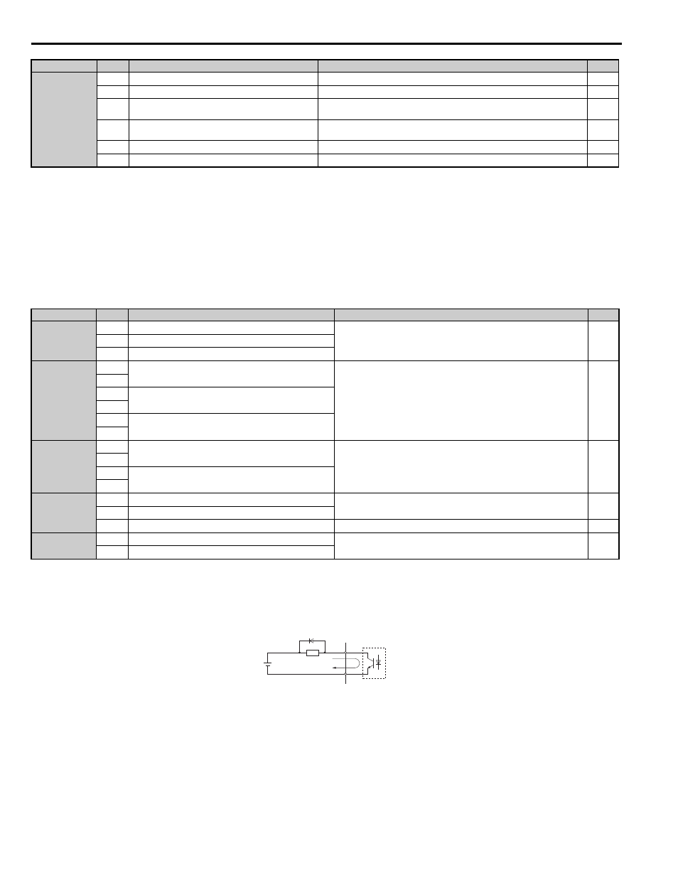
Figure 3.17
Figure 3.18 Connecting a Suppression Diode
Analog Inputs
+V
Power supply for analog inputs
10.5 Vdc (max allowable current 20 mA)
-V
Power supply for analog inputs
-10.5 Vdc (max allowable current 20 mA)
–
A1
Multi-function analog input 1 (Speed reference bias)
-10 to 10 Vdc, 0 to 10 Vdc (input impedance: 20 k
Ω)
A2
Multi-function analog input 2 (Not used)
-10 to 10 Vdc, 0 to 10 Vdc (input impedance: 20 k
Ω)
AC
Analog input common
0 V
E (G)
Ground for shielded lines and option cards
–
–
<1> Setting jumper S3 for an external power supply makes the wire jumper between terminals H1, H2, and HC ineffective. Remove the wire jumper
and connect an external power supply that can supply terminals H1, H2, and HC continuously.
Type
<1> Refrain from assigning functions to terminals M1 thru M6 that involve frequent switching, as doing so may shorten relay performance life.
Switching life is estimated at 200,000 times (assumes 1 A, resistive load).
<2> Connect a suppression diode as shown in
when driving a reactive load such as a relay coil. Make sure the diode rating is greater
than the circuit voltage.
No.
Terminal Name (Function)
Function (Signal Level) Default Setting
Page
Fault Relay
MA
N.O.
30 Vdc, 10 mA to 1 A; 250 Vac, 10 mA to 1 A
Minimum load: 5 Vdc, 10 mA
MB
N.C. output
MC
Fault output common
Multi-Function
Relay Output
M1
Multi-function relay output 1 (Brake release command)
Contact relay output
30 Vdc, 10 mA to 1 A
250 Vac, 10 mA to 1 A
Minimum load: 5 Vdc, 10 mA
M2
M3
Multi-function relay output 2 (Output contactor close command)
M4
M5
Multi-function relay output 3 (Drive ready)
M6
Multi-Function
Photocoupler
Output
P1
Photocoupler output 1 (During Frequency output)
48 Vdc, 2 to 50 mA
–
C1
P2
Photocoupler output 2 (Not Used/Through Mode)
C2
Monitor Output
FM
Analog monitor output 1 (Output speed)
-10 to +10 Vdc or 0 to +10 Vdc
AM
Analog monitor output 2 (Output current)
AC
Monitor common
0 V
–
Safety Monitor
Output
DM+
Safety monitor output
Outputs status of Safe Disable function. Closed when both Safe Disable
channels are closed. Up to +48 Vdc 50 mA
–
DM-
Safety monitor output common
A – External power, 48 V max.
C – Coil
B – Suppression diode
D – 50 mA or less
Type
No.
Terminal Name (Function)
Function (Signal Level) Default Setting
Page
A
B
C
D
YEA_common