For a d, H2: multi-function digital outputs, B.3 parameter table – Yaskawa L1000E AC Drive Technical Manual for CIMR-LE Models for Elevator Applications User Manual
Page 384
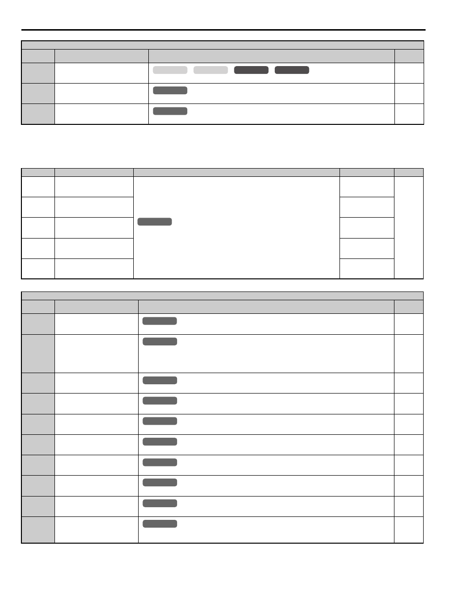
B.3 Parameter Table
384
YASKAWA ELECTRIC SIEP YAIL1E 01A YASKAWA AC Drive L1000E Technical Manual
■
H2: Multi-Function Digital Outputs
5C
Floor Sensor
Closed: Initiate Direct Landing (S5-10 = 1)
67
Communications Test Mode
Tests the MEMOBUS/Modbus RS-485/422 interface. Displays “PASS” if the test completes successfully.
79
Brake Feedback
Used for brake supervision and detection of incorrect operation.
<1> Motor Contactor Feedback (H1- = 56) = Normally open (N.O.).
<2> Brake Feedback (H1- = 79) = Normally open (N.O).
No.(Addr.)
Name
Description
Setting
Page
H2-01
(40BH)
Terminals M1-M2 Function
Selection (relay)
H2 Multi-Function Digital Output Settings on page 384
for a description of setting
values.
Default: 50
Min: 0
Max: 161
H2-02
(40CH)
Terminals M3-M4 Function
Selection (relay)
Default: 51
Min: 0
Max: 161
H2-03
(40DH)
Terminals M5-M6 Function
Selection (relay)
Default: 6
Min: 0
Max: 161
H2-04
(40EH)
Terminal P1-C1 Function
Selection (photocoupler)
Default: 37
Min: 0
Max: 161
H2-05
(40FH)
Terminal P2-C2 Function
Selection (photocoupler)
Default: F
Min: 0
Max: 161
H2 Multi-Function Digital Output Settings
H2-
Setting
Function
Description
Page
0
During Run
Closed: An Up/Down command is active or voltage is output.
1
Zero Speed
Open: Output speed is greater than the value of E1-09 (Minimum Output Frequency) or S1-01 (Zero Speed Level at
Stop).
Closed: Output frequency is less than or equal to the value of E1-09 (Minimum Output Frequency) or S1-01 (Zero
Speed Level at Stop).
2
Speed Agree 1
Closed: Output speed equals the speed reference (plus or minus the hysteresis set to L4-02).
3
User-set Speed Agree 1
Closed: Output speed and speed reference equal L4-01 (plus or minus the hysteresis set to L4-02).
4
Speed Detection 1
Closed: Output speed is less than or equal to the value in L4-01 with hysteresis determined by L4-02.
5
Speed Detection 2
Closed: Output speed is greater than or equal to the value in L4-01 with hysteresis determined by L4-02.
6
Drive Ready (READY)
Closed: Power up is complete and the drive is ready to accept an Up/Down command.
7
DC Bus Undervoltage
Closed: DC bus voltage is below the Uv trip level set in L2-05.
8
During Baseblock (N.O.)
Closed: Drive has entered the baseblock state (no output voltage).
9
Speed Reference Source
Open: The speed reference is supplied by an external reference (set in b1-01).
Closed: Digital operator supplies the speed reference.
H1 Multi-Function Digital Input Settings
H1-
Setting
Function
Description
Page
CLV
CLV/PM
V/f
OLV
common
_
All Modes
common
_
All Modes
common
_
All Modes
common
_
All Modes
common
_
All Modes
common
_
All Modes
common
_
All Modes
common
_
All Modes
common
_
All Modes
common
_
All Modes
common
_
All Modes
common
_
All Modes
common
_
All Modes
common
_