F3: digital input card (di-a3), F4: analog monitor card (ao-a3), B.3 parameter table – Yaskawa L1000E AC Drive Technical Manual for CIMR-LE Models for Elevator Applications User Manual
Page 380
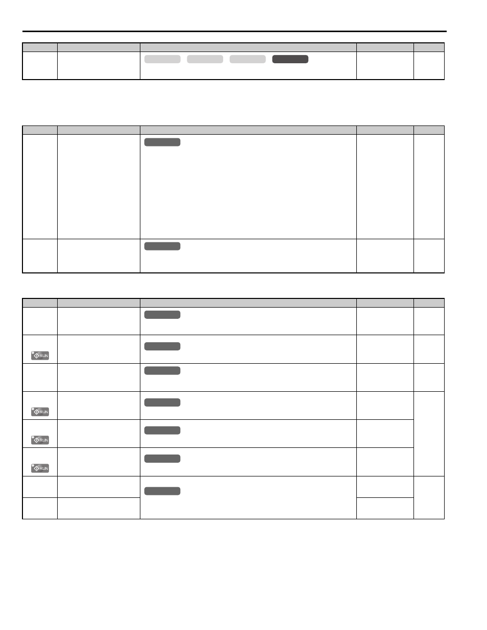
B.3 Parameter Table
380
YASKAWA ELECTRIC SIEP YAIL1E 01A YASKAWA AC Drive L1000E Technical Manual
■
F3: Digital Input Card (DI-A3)
■
F4: Analog Monitor Card (AO-A3)
F1-66 to
F1-81
(B9AH to
BA9H)
PG-E3 Encoder Adjust 1 to 16
Sets encoder offsets 1 to 16 for the PG-E3 option card. These parameters are automatically set
by the execution of Auto-Tuning of PG-E3 encoder characteristics.
Default: 0
Min: 0
Max: FFFF
<1> Default setting is determined by the control mode (A1-02).
<2> Setting range is 1 to 15000 ppr when the drive is set for CLV/PM.
No.(Addr.)
Name
Description
Setting
Page
F3-01
(390H)
DI-A3 Option Card Input Selection
0: BCD, 1% units
1: BCD, 0.1% units
2: BCD, 0.01% units
3: BCD, 1 Hz units
4: BCD, 0.1 Hz units
5: BCD, 0.01 Hz units
6: BCD customized setting (5 digit), 0.02 Hz units
7: Binary input
The unit and the setting range are determined by F3-03.
F3-03 = 0: 255/100% (-255 to +255)
F3-03 = 1: 40961/100% (-4095 to +4095)
F3-03 = 2: 30000/100% (-33000 to +33000)
When the digital operator units are set to be displayed in Hertz or user-set units (o1-03 = 2 or 3),
the units for F3-01 are determined by parameter o1-03.
Default: 0
Min: 0
Max: 7
F3-03
(3B9H)
DI-A3 Option Card Data Length
Selection
0: 8 bit
1: 12 bit
2: 16 bit
Default: 2
Min: 0
Max: 2
No.(Addr.)
Name
Description
Setting
Page
F4-01
(391H)
Terminal V1 Function Selection
Sets the monitor signal for output from terminal V1. Set this parameter to the last three digits of
the desired U- monitor. Some U parameters are available only in certain control modes.
Default: 102
Min: 000
Max: 999
F4-02
(392H)
Terminal V1 Gain
Sets the gain for voltage output via terminal V1.
Default: 100.0%
Min: -999.9%
Max: 999.9%
F4-03
(393H)
Terminal V2 Function Selection
Sets the monitor signal for output from terminal V2. Set this parameter to the last three digits of
the desired U- monitor. Some U parameters are available only in certain control modes.
Default: 103
Min: 000
Max: 999
F4-04
(394H)
Terminal V2 Gain
Sets the gain for voltage output via terminal V2.
Default: 50.0%
Min: -999.9%
Max: 999.9%
F4-05
(395H)
Terminal V1 Bias
Sets the amount of bias added to the voltage output via terminal V1.
Default: 0.0%
Min: -999.9%
Max: 999.9%
F4-06
(396H)
Terminal V2 Bias
Sets the amount of bias added to the voltage output via terminal V2.
Default: 0.0%
Min: -999.9%
Max: 999.9%
F4-07
(397H)
Terminal V1 Signal Level
Selection
0: 0 to 10 V
1: -10 to 10 V
Default: 1
Min: 0
Max: 1
F4-08
(398H)
Terminal V2 Signal Level
Selection
Default: 1
Min: 0
Max: 1
No.(Addr.)
Name
Description
Setting
Page
common
_
CLV
CLV/PM
V/f
OLV
All Modes
common
_
All Modes
common
_
All Modes
common
_
All Modes
common
_
All Modes
common
_
All Modes
common
_
All Modes
common
_
All Modes
common
_
All Modes
common
_