Broadcast messages, Fault trace contents, Broadcast messages fault trace contents – Yaskawa L1000E AC Drive Technical Manual for CIMR-LE Models for Elevator Applications User Manual
Page 439: Table c.4 fault trace / history register contents
C.9 MEMOBUS/Modbus Data Table
YASKAWA ELECTRIC SIEP YAIL1E 01A YASKAWA AC Drive L1000E Technical Manual
439
MEMOBUS
/Mo
dbu
s
C
o
m
m
u
ni
ca
ti
on
s
C
◆ Broadcast Messages
Data can be written from the master to all slave devices at the same time.
The slave address in a broadcast command message must be set to 00H. All slaves will receive the message, but will not
respond.
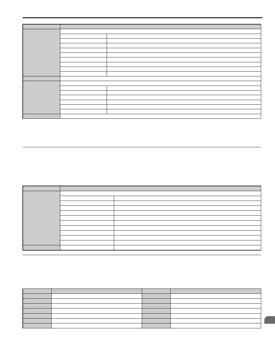
◆ Fault Trace Contents
The table below shows the fault codes that can be read out by MEMOBUS/Modbus commands from the U2- monitor
parameters.
Table C.4 Fault Trace / History Register Contents
00E2H
oFC1x Contents (CN5-C)
bit 0
Option RAM Fault (oFC10)
bit 1
Option Operation Mode Fault (SLMOD) (oFC11)
bit 2
Drive Receive CRC Error (oFC12)
bit 3
Drive Receive Frame Error (oFC13)
bit 4
Drive Receive Abort Error (oFC14)
bit 5
Option Receive CRC Error (oFC15)
bit 6
Option Receive Frame Error (oFC16)
bit 7
Option Receive Abort Error (oFC17)
bit 8 to F
Reserved
00E3H
Reserved
00E4H
oFC5x Contents (CN5-C)
bit 0
oFC50 (Encoder Option AD Conversion Error)
bit 1
oFC51 (Encoder Option Analog Circuit Error)
bit 2
oFC52 (Encoder Communication Timeout)
bit 3
oFC53 (Encoder Communication Data Error)
bit 4
oFC54 (Encoder Error)
bit 5 to F
Reserved
00E5H to 00FFH
Reserved
<1> Parameter o1-03, Digital Operator Display Selection, determines the units.
<2> The display resolution depends on the rated output power of the drive. Models 2A0018 to 2A0041 and 4A0009 to 4A0023 display values in
0.01 A units, while models 2A0059 to 2A0432 and 4A0030 to 4A0260 display values in 0.1 A units.
<3> Communication error contents are saved until the fault is reset.
<4> Set the number of motor poles to parameter E2-04, E4-04, or E5-05 depending on the motor being used.
Register No.
Contents
0001H
Digital Input Command
bit 0
Up/Down Command (0: Run 1: Stop)
bit 1
Direction Command (0: Down, 1: Up)
bit 2, 3
Reserved
bit 4
External Fault
bit 5
Fault Reset
bit 6 to B
Reserved
bit C
Multi-Function Digital Input S5
bit D
Multi-Function Digital Input S6
bit E
Multi-Function Digital Input S7
bit F
Multi-Function Digital Input S8
0002H
Speed Reference
100%
Fault Code
Fault Name
Fault Code
Fault Name
0002H
Undervoltage (Uv1)
009DH
ASIC PWM Pattern Error (CPF28)
0003H
Control Power Supply Undervoltage (Uv2)
009EH
ASIC On-Delay Error (CPF29)
0004H
Soft Charge Circuit Fault (Uv3)
009FH
ASIC BBON Error (CPF30)
0005H
Short Circuit (SC)
00A0H
ASIC Code Error (CPF31)
0006H
Ground Fault (GF)
00A1H
ASIC Start-p Error (CPF32)
0007H
Overcurrent (oC)
00A2H
Watch-dog Error (CPF33)
0008H
Overvoltage (ov)
00A3H
ASIC Power/Clock Error (CPF34)
Register No.
Contents