7 setup troubleshooting and possible solutions – Yaskawa L1000E AC Drive Technical Manual for CIMR-LE Models for Elevator Applications User Manual
Page 146
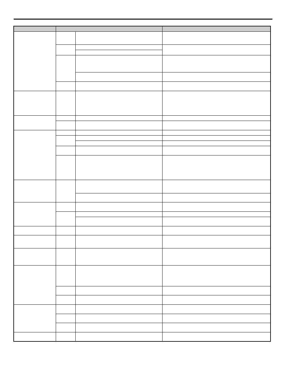
4.7 Setup Troubleshooting and Possible Solutions
146
YASKAWA ELECTRIC SIEP YAIL1E 01A YASKAWA AC Drive L1000E Technical Manual
Motor stops shortly (under-
shoot) when the leveling
speed is reached.
V/f and OLV Not enough torque at low speed.
Increase the Minimum and Middle Voltage Levels for the V/f pattern voltage
(E1-10 and E1-08 respectively). Make sure that the Starting and Leveling
Current does not rise too high.
OLV and
CLV
Motor data incorrect.
Adjust the motor data (E2-
), especially the motor slip (E2-02) and no-
load current values (E2-03), or perform Auto-Tuning.
Too much slip compensation.
CLV
CLV/PM
Speed control loop responds too slow.
Increase the Speed Control Gain and reduce the Speed Control Integral Time
used for Low Speed at Stop. The parameters to be changed depend on the set-
ting of C5-05 and whether a third set of speed loop settings is used. Refer to
Speed Loop Adjustments (CLV and CLV/PM) on page 130
.
The inertia compensation function is not set up correctly.
If the Inertia Compensation Function is used (n5-01 = 1) make sure the values
in n5-02 and n5-03 are correct.
All
The deceleration rate changes too quickly when reaching
leveling speed.
Decrease the Jerk at the End of Deceleration. Decrease C2-04 if set in m/s
2
,
increase C2-04 if set in s.
Motor speed overshoot at
acceleration end and under-
shoot when reaching leveling
speed occurs. Problem can
not be resolved by adjusting
the speed loop.
CLV
CLV/PM
Inertia is high.
Use the Inertia Compensation Function. Set n5-01 to 1 and then adjust param-
eters n5-02 and n5-03 as described in
Inertia Compensation (CLV and CLV/
.
Motor or machine vibrates at
high speed or top speed.
OLV
Torque compensation responds too quickly.
Increase the Torque Compensation Delay Time (C4-02).
CLV
CLV/PM
Speed control loop adjusted too hard.
Decrease C5-01, then increase C5-02.
Motor or machine vibrates in
the low or medium speed
range.
V/f
Output voltage is too high.
Reduce the V/f Pattern settings (E1-08, E1-10).
OLV
Torque compensation is responding too quickly.
Increase the Torque Compensation Delay Time (C4-02).
Output voltage is too high.
Reduce the V/f Pattern settings (E1-08, E1-10).
OLV
CLV
The value for the motor slip is set incorrectly.
Check the Motor Slip value in parameter E2-02. Increase or decrease it in
steps of 0.2 Hz.
CLV
CLV/PM
Speed control loop adjusted with too much gain.
• Decrease C5-01 and then increase C5-02 if the problem occurs at speed
higher than C5-07.
• Decrease C5-03 and then increase C5-04 if the problem occurs at speed
lower than C5-07.
• Decrease C5-13 and then increase C5-14 if the problem occurs at speed
lower than C5-07 but only during deceleration.
Motor or machine vibrates in
During Position Lock.
CLV
CLV/PM
The Position Lock control loop does not respond fast enough.
• If vibration occurs at During Position Lock at start, first decrease S3-02. If
decreasing S3-02 does not resolve the problem, decrease S3-01.
• Decrease S3-03 if vibration occurs During Position Lock at stop.
The speed control is not responding quickly enough when the
brake is released.
Decrease C5-19 and then increase C5-20.
Vibrations with the fre-
quency equal to the motor
speed occur.
CLV
CLV/PM
Encoder vibrates.
Check the encoder mounting and the alignment of encoder and motor shaft.
All
Mechanical problems.
Check bearings and gearbox.
Rotational parts (motor armature, handwheel, brake disk/
drum) are not properly balanced.
Properly balance rotating parts.
Oscillations when using an
analog speed reference.
All
The analog reference value is not stable or the signal is noisy.
• Check the analog signal line connection. Use shielded twisted pair cables.
• Apply a filter to the analog input signal by setting parameter H3-13.
Top speed is different in
motoring and regenerative
mode.
OLV
Slip Compensation during Regenerative operation is switched
off.
Make sure C3-04 is set properly and set parameter C3-05 to 0.
Speed reference and motor
speed do not match when
using an analog reference
signal.
All
The drives analog input is not set according to the signal level
of the controller speed reference output signal.
Check the gain and bias settings for the analog input that is used to set the
speed reference. Check parameters H3-03 and H3-04 for input A1, check
parameters H3-11 and H3-12 for input A2.
Acceleration is longer than
set to C1- parameters.
All
The load is too high.
• Check if the acceleration rate set is not too high (acceleration time is too
short).
• Make sure the drive rated current is enough to fulfill the application
requirements.
• Make sure the load is not seized, car guide lubrication is ok, etc.
V/f and OLV
The load is too high and the current/torque exceeds the stall
prevention level.
Check if the Stall Prevention Level at Acceleration in L3-03 is not set too
small.
OLV, CLV
CLV/PM
The load is too high and the torque exceeds the drives torque
limits.
Check it the Torque Limit parameters L7- are not set too low.
Motor speed does not match
the speed reference at con-
stant speed.
All
The load is too high.
Make sure the drive rated current is enough to fulfill the application require-
ments.
V/f
The load is too high and the current/torque exceeds the stall
prevention level.
Check if the Stall Prevention Level During Run in L3-06 is not set too low.
OLV, CLV
CLV/PM
The load is too high and the torque exceeds the torque limits.
Check it the Torque Limit parameters L7- are not set too low.
High frequency acoustic
noise from the motor.
All
The carrier frequency is too low.
Increase the Carrier Frequency in parameter C6-03. If the carrier frequency is
set higher than the default setting, a current derating must be considered.
Problem
Control Mode and Possible Cause
Corrective Action