S2: slip compensation for elevators, B.3 parameter table – Yaskawa L1000E AC Drive Technical Manual for CIMR-LE Models for Elevator Applications User Manual
Page 398
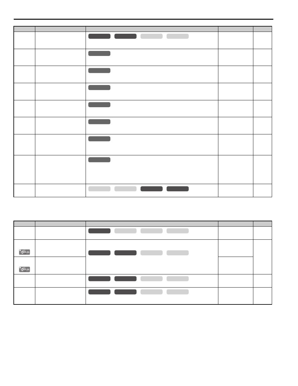
B.3 Parameter Table
398
YASKAWA ELECTRIC SIEP YAIL1E 01A YASKAWA AC Drive L1000E Technical Manual
■
S2: Slip Compensation for Elevators
S1-03
(682H)
DC Injection Current at Stop
Determines the amount of current to use for DC Injection at stop. Set as a percentage of the
drive rated current.
Default: 50%
Min: 0%
Max: 100%
S1-04
(683H)
DC Injection/Position Lock Time
at Start
Determines how long the drive should perform DC Injection at start. In CLV and CLV/PM, S1-
04 determines how long Position Lock should be performed. A setting of 0.00 disables S1-04.
Default: 0.40s
Min: 0.00 s
Max: 10.00 s
S1-05
(684H)
DC Injection/Position Lock Time
at Stop
Determines how long the drive should perform DC Injection at stop. In CLV and CLV/PM, S1-
05 determines how long Position Lock should be performed. A setting of 0.00 disables S1-05.
Default: 0.60s
Min: 0.00 s
Max: 10.00 s
S1-06
(685H)
Brake Release Delay Time
Determines the delay time between the start of DC injection/Position Lock and setting the brake
control command (H2-=50) in order to release the brake at the beginning of the ride.
Default: 0.20s
Min: 0.00 s
Max: 10.00 s
S1-07
(686H)
Brake Close Delay Time
Determines the delay time between reaching Zero Speed (S1-01) and resetting the brake control
command (H2- = 50) in order to apply the brake at the end of the ride.
Default: 0.10s
Min: 0.00 s
Max:
[S1-05]
S1-10
(687H)
Run Command Delay Time
Sets the time that must pass after the Up/Down command is entered until the drive internal Run
command is set and the ride is started.
Default: 0.10s
Min: 0.00 s
Max: 1.00 s
S1-11
(688H)
Output Contactor Open Delay
Time
Determines the delay time between shutting off the output of the drive and resetting the
contactor control command (H2- = 51) in order to release the motor contactor after a ride
has finished.
Default: 0.10s
Min: 0.00 s
Max: 1.00 s
S1-12
(6E0H)
Motor Contactor Control During
Auto-Tuning
Determines the state of the output contactor control command (H2- = 51) during Auto-
Tuning.
0: Disabled
1: Enabled
2: Enabled during Auto-Tuning and HBB
Default: 0
Min: 0
Max: 2
S1-26
(6D7H)
Emergency Stop Start Level
Sets the Emergency Stop Start Level as a percentage of the Maximum Output Frequency.
Default: 10.0 %
Min: 0.0 %
Max: 100.0 %
<1> Default setting is determined by the control mode (A1-02).
No. (Addr.)
Name
Description
Setting
Page
S2-01
(68FH)
Motor Rated Speed
Sets the motor rated speed.
Default: 1380 rpm
Min: 300 rpm
Max: 1800 rpm
S2-02
(690H)
Slip Compensation Gain in
Motoring Mode
Slip compensation for leveling speed can be set separately for motoring and regenerative states.
This can help improve the accuracy of leveling.
Default: 0.7
Min: 0.0
Max: 5.0
S2-03
(691H)
Slip Compensation Gain in
Regenerative Mode
Default: 1.0
Min: 0.0
Max: 5.0
S2-05
(693H)
Slip Compensation Torque
Detection Delay Time
Sets a delay time before detecting torque for slip compensation.
Default: 1000 ms
Min: 0 ms
Max: 10000 ms
S2-06
(694H)
Slip Compensation Torque
Detection Filter Time Constant
Sets the filter time constant applied to the torque signal used for the slip compensation value
calculation.
Default: 500 ms
Min: 0 ms
Max: 2000 ms
No. (Addr.)
Name
Description
Setting
Page
common
_
CLV
CLV/PM
V/f
OLV
All Modes
common
_
All Modes
common
_
All Modes
common
_
All Modes
common
_
All Modes
common
_
All Modes
common
_
All Modes
common
_
common
_
CLV
CLV/PM
V/f
OLV
common
_
CLV
CLV/PM
V/f
OLV
common
_
CLV
CLV/PM
V/f
OLV
common
_
CLV
CLV/PM
V/f
OLV
common
_
CLV
CLV/PM
V/f
OLV