H3: multi-function analog inputs, B.3 parameter table – Yaskawa L1000E AC Drive Technical Manual for CIMR-LE Models for Elevator Applications User Manual
Page 386
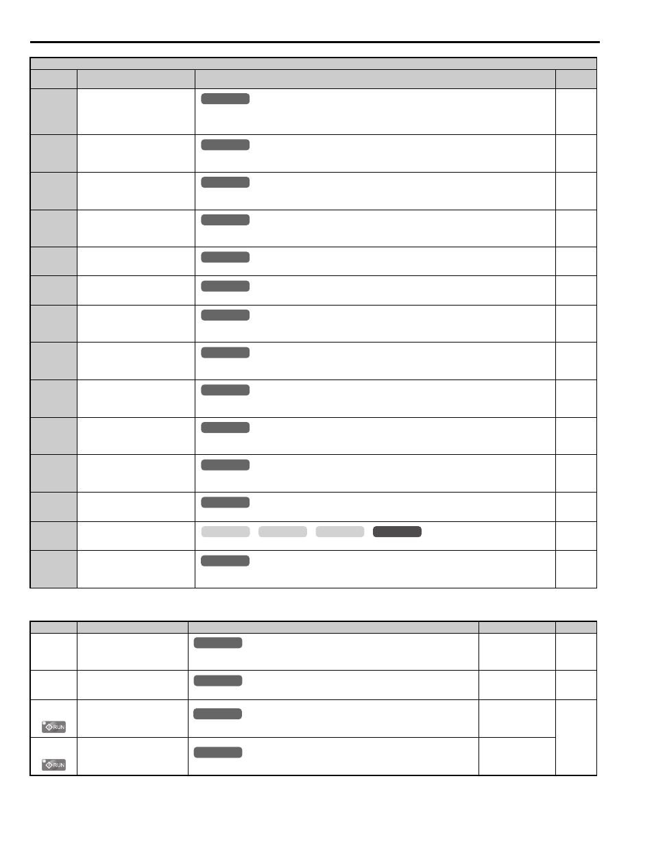
B.3 Parameter Table
386
YASKAWA ELECTRIC SIEP YAIL1E 01A YASKAWA AC Drive L1000E Technical Manual
■
H3: Multi-Function Analog Inputs
37
During Frequency Output
Open: No frequency output from drive when stopped with baseblock, stopped with DC injection braking during initial
excitation, or stopped with short circuit braking.
Closed: Drive is outputting a frequency.
47
Input Phase Loss
Closed: Input phase loss has occurred
Open: Normal operation (no phase loss detected)
4E
Braking Transistor Fault (rr)
Closed: The built-in dynamic braking transistor failed.
Note: This function is not available in models 2A0181 to 2A0432 and 4A0094 to 4A0260.
50
Brake Control
Close: Release brake
Open: Apply brake
51
Output Contactor Control
Closed: Close output contactor
52
Door Zone Reached
Closed: Indicates that the door zone has been reached.
53
Not Zero Speed
Closed: Speed is greater than the zero speed level set to S1-01
Open: Operating at zero speed level
54
Light Load Direction
Closed: Light load direction is up
Open: Light load direction is down
55
Light Load Direction Detection
Status
Closed: Ready for Light Load Direction Search
Open: Light Load Detection in progress
58
Safe Disable Status
Closed: Safe Disable terminals H1-HC and H2-HC are open, drive is in a baseblock state
Open: Safe Disable terminals H1-HC and H2-HC are closed (normal operation)
5C
Motor Current Monitor
Open: Output current is greater than the value of L8-99
Closed: Output current is less than or equal to the value of L8-99
60
Internal Cooling Fan Alarm
Closed: Internal cooling fan alarm
61
Motor Pole Search Status
Closed: Motor pole search successful
100 to 161
Function 0 to 61 with Inverse Output
Inverts the output switching of the multi-function output functions.
Sets the last two digits of 1 to reverse the output signal of that specific function.
No.(Addr.)
Name
Description
Setting
Page
H3-01
(410H)
Terminal A1 Signal Level
Selection
0: 0 to 10 V
1: –10 to 10 V
Default: 0
Min: 0
Max: 1
H3-02
(434H)
Terminal A1 Function Selection
Sets the function of terminal A1.
Default: 0
Min: 0
Max: 1F
H3-03
(411H)
Terminal A1 Gain Setting
Sets the level of the input value selected in H3-02 when 10 V is input at terminal A1.
Default: 100.0%
Min: -999.9%
Max: 999.9%
H3-04
(412H)
Terminal A1 Bias Setting
Sets the level of the input value selected in H3-02 when 0 V is input at terminal A1.
Default: 0.0%
Min: -999.9%
Max: 999.9%
H2 Multi-Function Digital Output Settings
H2-
Setting
Function
Description
Page
All Modes
common
_
All Modes
common
_
All Modes
common
_
All Modes
common
_
All Modes
common
_
All Modes
common
_
All Modes
common
_
All Modes
common
_
All Modes
common
_
All Modes
common
_
All Modes
common
_
All Modes
common
_
common
_
CLV
CLV/PM
V/f
OLV
All Modes
common
_
All Modes
common
_
All Modes
common
_
All Modes
common
_
All Modes
common
_