F4: analog monitor card settings, F3-03: di-a3 option card data length selection, 6 f: option settings – Yaskawa L1000E AC Drive Technical Manual for CIMR-LE Models for Elevator Applications User Manual
Page 190: Terminal v2 1
5.6 F: Option Settings
190
YASKAWA ELECTRIC SIEP YAIL1E 01A YASKAWA AC Drive L1000E Technical Manual
Note: BCD input when o1-03 = 2 or 3. Units are determined by o1-03.
■
F3-03: DI-A3 Option Card Data Length Selection
Determines the number of bits for the option card input that sets the speed reference.
Setting 0: 8 bit
Setting 1: 12 bit
Setting 2: 16 bit
◆ F4: Analog Monitor Card Settings
These parameters set up the drive for operation with the analog output option card AO-A3. Refer to the instruction
manual packaged with the option card for specific details on installation, wiring, input signal level selection, and
parameter setup.
■
F4-01, F4-03: Terminal V1, V2 Function Selection
Selects the data to output from analog terminal V1. Enter the final three digits of U- to determine which monitor
data is output from the option card. Some monitors are only available in certain control modes.
■
F4-02, F4-04, F4-05, F4-06: Terminal V1, V2 Gain and Bias
Parameters F4-02 and F4-04 determine the gain, while parameters F4-05 and F4-06 set the bias. These parameters are set
as a percentage of the output signal from V1 and V2 where 100% equals 10 V output. The terminal output voltage is
limited to 10 V.
Using Gain and Bias to Adjust Output Signal Level
The output signal is adjustable while the drive is stopped.
Terminal V1
1.
View the value set to F4-02 (Terminal V1 Monitor Gain) on the digital operator. A voltage equal to 100% of the
parameter being set in F4-01 is output at terminal V1.
2.
Adjust F4-02 while viewing the monitor connected to the terminal V1.
3.
View the value set to F4-05 on the digital operator. Terminal V1 outputs a voltage equal to 0% of the monitor
selected by the setting value of F4-01.
4.
Adjust F4-05 while viewing the output signal on the terminal V1.
Terminal V2
1.
View the value set to F4-02 (Terminal V2 Monitor Gain) on the digital operator. A voltage equal to 100% of the
parameter being viewed in F4-03 is output at terminal V2.
2.
Adjust F4-04 while viewing the monitor connected to the terminal V2.
3.
View the value set to F4-06 on the digital operator. Terminal V2 will output a voltage equal to 0% of the monitor
selected by the setting value of F4-03.
4.
Adjust F4-06 while viewing the output signal on the terminal V2.
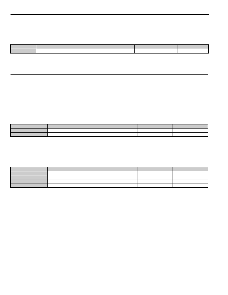
No.
Parameter Name
Setting Range
Default
F3-03
DI-A3 Option Card Data Length Selection
0 to 2
2
No.
Parameter Name
Setting Range
Default
F4-01
Terminal V1 Function Selection
000 to 999
102
F4-03
Terminal V2 Function Selection
000 to 999
103
No.
Parameter Name
Setting Range
Default
F4-02
Terminal V1 Gain
-999.9 to 999.9%
100.0%
F4-04
Terminal V2 Gain
-999.9 to 999.9%
50.0%
F4-05
Terminal V1 Bias
-999.9 to 999.9%
0.0%
F4-06
Terminal V2 Bias
-999.9 to 999.9%
0.0%