6 setup procedure for elevator applications, Refer to figure 4.25 for a wiring diagram, Starting rescue operation 1 – Yaskawa L1000E AC Drive Technical Manual for CIMR-LE Models for Elevator Applications User Manual
Page 133: Ending rescue operation 1
4.6 Setup Procedure for Elevator Applications
YASKAWA ELECTRIC SIEP YAIL1E 01A YASKAWA AC Drive L1000E Technical Manual
133
St
ar
t-
U
p
Pr
og
ra
m
m
in
g
&
Op
er
at
io
n
4
■
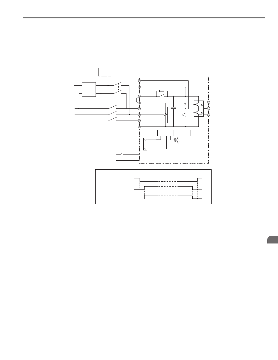
Using a Single-Phase, 230 Vac UPS (Uninterruptable Power Supply)
Follow the instructions when using a single-phase 230 V UPS for Rescue Operation. A 230 V UPS can be used for both
200 V and 400 V class drives.
Wiring
Refer to
Figure 4.20
Figure 4.25 Using a Single-Phase 230 V UPS
Operation Sequence
Starting Rescue Operation
1.
Open contactor B.
2.
Set the input terminal programmed for Rescue Operation (H1- = 55).
3.
Close contactor A.
4.
Set the Up/Down command.
Ending Rescue Operation
1.
After the car has stopped open contactor A.
2.
Clear the input terminal set for Rescue Operation (H1- = 55).
3.
Close contactor B to return to operation with normal power supply.
Application Precautions
The drive may fault on a control power supply fault (Uv2) if the UPS can’t provide enough voltage, or if the Light Load
Direction Search is not set properly. If this problem occurs, take the following corrective actions:
Corrective Action:
• Use a separate battery for the controller power supply.
-
L1000E
Magnetic Contactor Sequence
H1-
ڧڧ = 55
(Rescue Operation)
sine wave
230 Vac
single-phase
H1-
ڧڧ = 55
(Rescue Operation)
L1
L2
L3
N
R/L1
S/L2
T/L3
CN19
S
3
to S
8
1
4
SC
+1
+2
B2
W/T3
V/T2
U/T1
Magnetic
Contactor B
Magnetic
Contactor A
UPS
Magnetic Contactor B
Magnetic Contactor A
Elevator
control
system
Control
circuit
Power supply