Refer to, For details, Connecting the drive and battery – Yaskawa L1000E AC Drive Technical Manual for CIMR-LE Models for Elevator Applications User Manual
Page 137: 6 setup procedure for elevator applications
4.6 Setup Procedure for Elevator Applications
YASKAWA ELECTRIC SIEP YAIL1E 01A YASKAWA AC Drive L1000E Technical Manual
137
St
ar
t-
U
p
Pr
og
ra
m
m
in
g
&
Op
er
at
io
n
4
■
Connecting the Drive and Battery
Use the 1.1 m cable packaged with the drive to connect the battery. Remove the connector covering port CN19 before
connecting the cable to CN19.
Information on battery power ratings can be found in
.
Note: The connector port location and angle vary by drive model.
DANGER! Switch off the power supply before wiring and connecting the battery cable. Failure to comply will lead to death or serious
injury from electric shock.
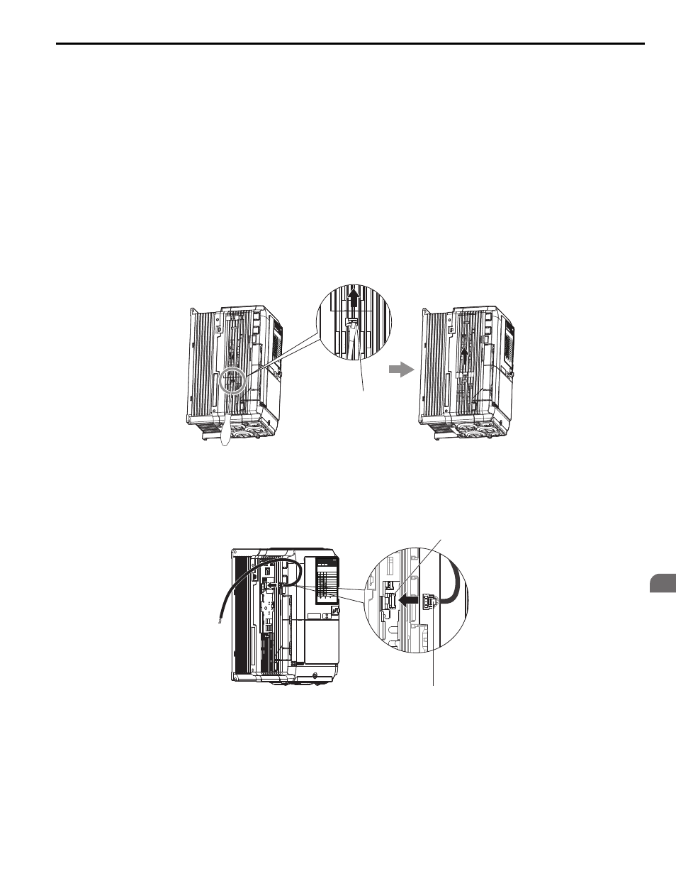
Battery Connections for 2A0018 to 2A0094 and 4A0009 to 4A0049
1.
Insert the tip of a screwdriver into the opening on the edge of the CN19 connector cover. Slide the cover off the
drive as indicated in
NOTICE: A straight-edge screwdriver should be inserted into the opening provided on the connector cover at the proper angle.
Attempting to insert the screwdriver blade at a different angle could damage the drive.
Figure 4.24
Figure 4.29 Removing the Connector Cover
2.
Connect the cable provided to the CN19 port.
NOTICE: Be sure that the connector fastens at the correct angle to the drive port. The incorrect angle could damage the battery, cable,
or connector.
Figure 4.25
Figure 4.30 Connecting the Cable
PWR
LED MO
NITOR JV
OP-184
RUN
DS1
DS2
RUN
DS1
DS2
STATUS
READY
RUN
ALARM(R
UN)
PGOH,L
T
BB,HBB
EF,SE
Other Fa
ult
OV,UV
OH,OL
OC,GF,S
C,PGO
CPF,OFA
,OFB,OF
C
:LIGHT
:BLINK
:LIGHT O
FF
PWR
LED MO
NITOR JV
OP-184
RUN
DS1
DS2
RUN
DS1
DS2
STATU
S
READY
RUN
ALARM(R
UN)
PGOH,L
T
BB,HBB
EF,SE
Other Fa
ult
OV,UV
OH,OL
OC,G
F,SC,P
GO
CPF,OFA,
OFB,OFC
:LIGHT
:BLINK
:LIGHT O
FF
Press inwards on the tab and
slide the connector cover in the
direction indicated by the arrow.
PWR
LED MONITOR JVOP-184
RUN DS1
DS2
RUN DS1 DS2
STATUS
READY
RUN
ALARM(RUN)
PGOH,LT
BB,HBB
EF,SE
Other Fault
OV,UV
OH,OL
OC,GF,SC,PGO
CPF,OFA,OFB,OFC
:LIGHT :BLINK :LIGHT OFF
Press in on the connector
clip to plug in the cable.
Port CN19